What was the plan?
The other day I came across a picture of a vintage Fisher Price Snoopy Sniffer toy dog to pull along. Fuzzy childhood memories surfaced of having once seen one of these in action, with its doleful eyes and slightly frantic leg movement. Of course I couldn’t resist having a go at producing my own version, with a handle to crank so that I could admire it in one place on a convenient table, instead of having to scamper around with my nose to the floor risking a hay fever attack from low-level dust mites.
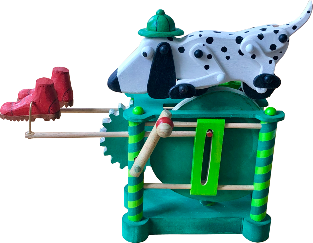
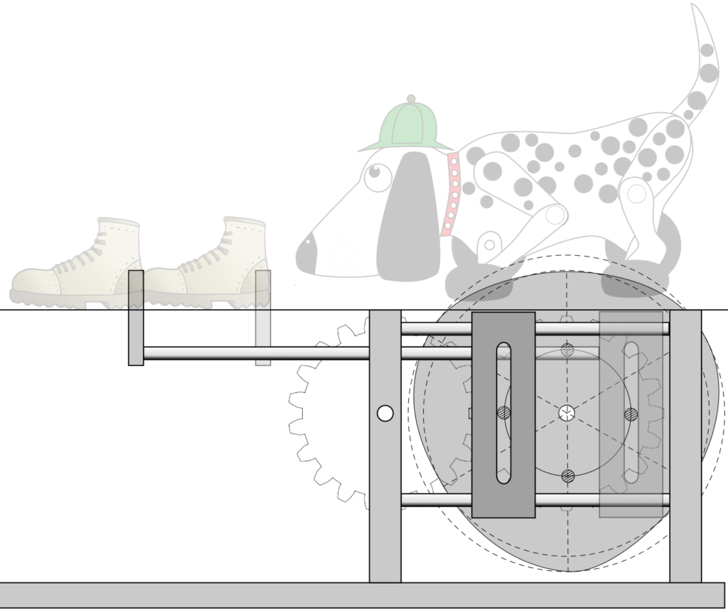
I had always thought of this as a bloodhound, probably used every day by Sherlock Holmes pursuing his Victorian Villains through the wild English countryside. A deer-stalker hat was thus indispensable! As far as a Victorian Villain was concerned, I thought I would take a minimalist approach and just show his boots. Maybe Sherlock is after the invisible man, who unfortunately has to wear sensible boots to carry out his villainous deeds?
To keep Sherlock’s Snooper Sniffing dog in one place, its wheels run along a rotating, slightly irregular cam, to make the movement uneven and so more interesting. As this cam turns, a pin protruding from its face drives a rod backwards and forwards to which a boot is attached. A realistic walking movement would see the boots not just move forwards and backwards, but also up and down. I’m afraid that my minimalist, invisible villain rather drags his feet and doesn’t lift them at all. I made the boots free swinging and, if you scrunch your eyes almost closed, you can imagine that it could actually be someone walking.
The dog’s design
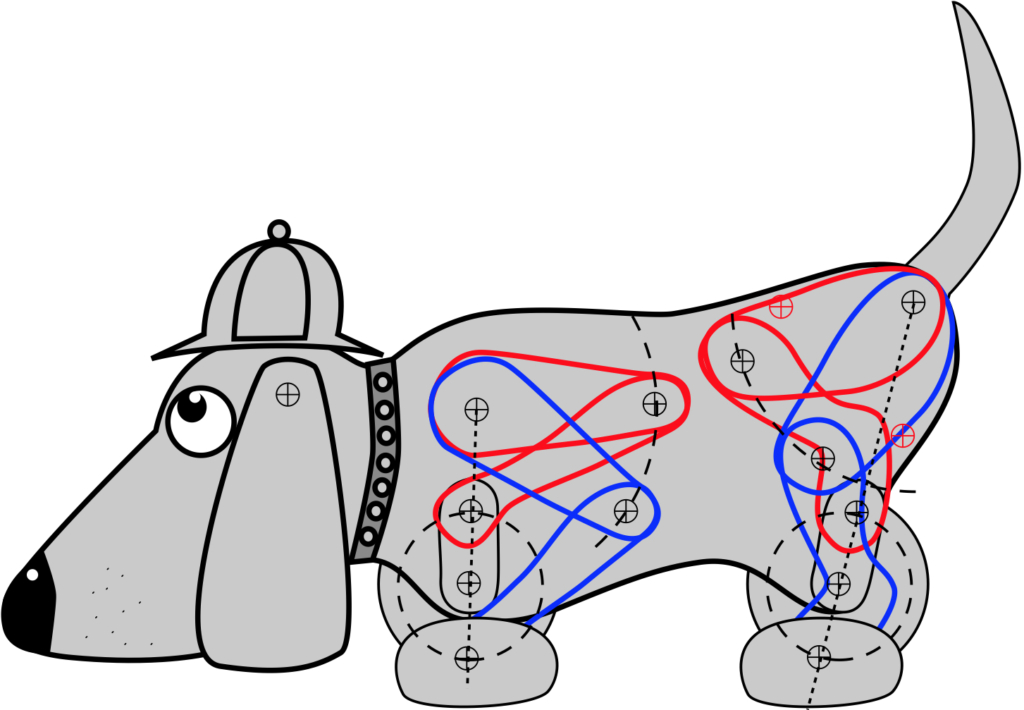
A super sensitive nose close to the ground and an expressive tail are vital accoutrements for our canine sleuth. On a more practical level, its paws have to be moved in a circular motion via the wheel inside the dog’s body. As the paws move, the leg attached to the paw flexes and the elbow moves up and down, moving in an arc relative to the shoulder pivot. I drew the highest position in red and the lowest in blue. This was helpful to check that the front and rear legs don’t collide. When I was satisfied with that, it was then easy to dismantle the drawing to show the parts.
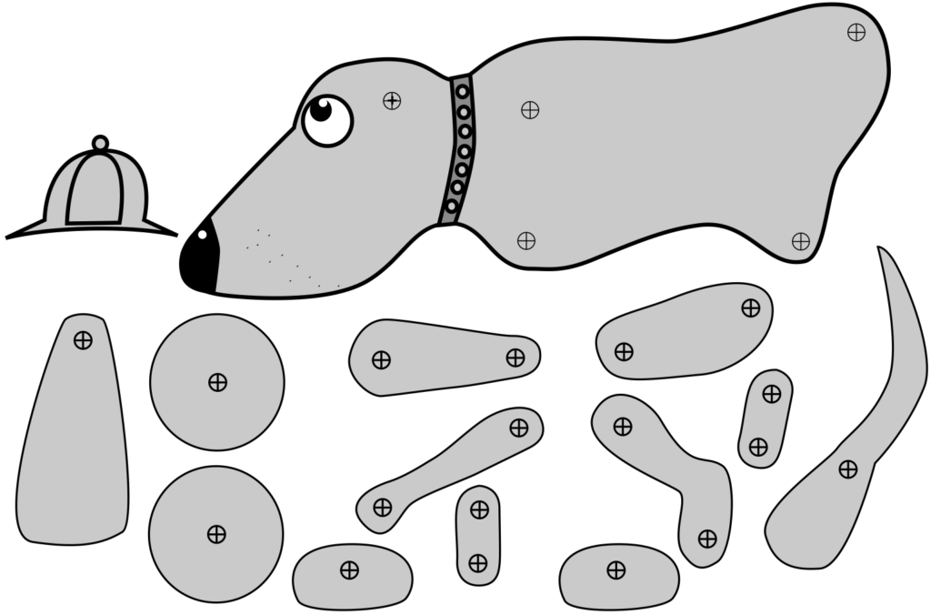
Printed out on some stiffish card, these can be cut out as templates.
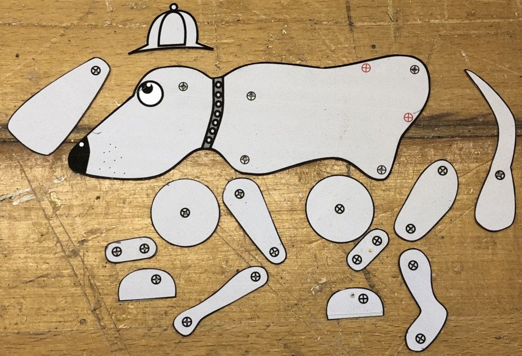
Use the templates to mark some plywood, drill the holes and cut the pieces. One tail, four paws and two of everything else.
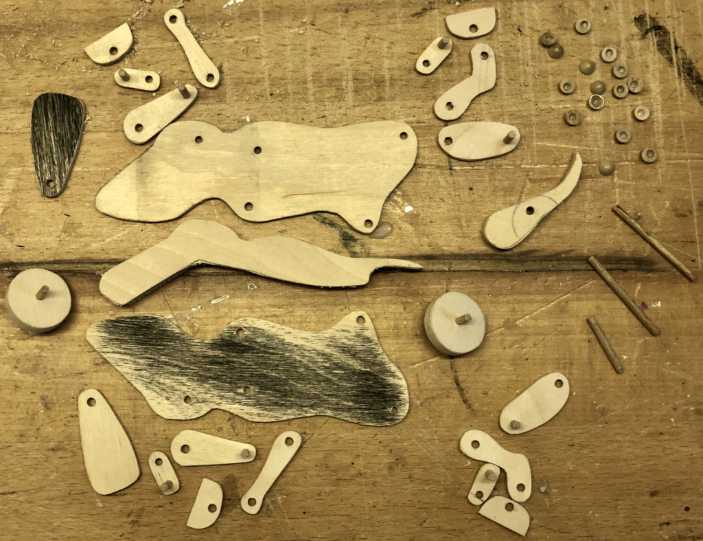
Most parts are in 3 mm plywood. The wheels are 6 mm plywood, so the two halves have to be kept 8 mm apart by a spacer which has the same shape as the top section of the sides. This also leaves space for the tail to swing around a bit.
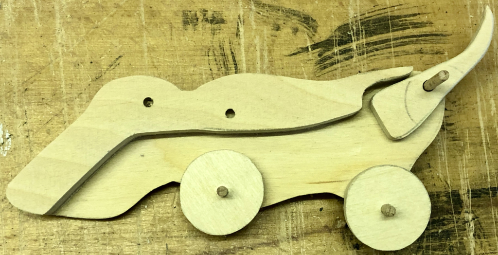
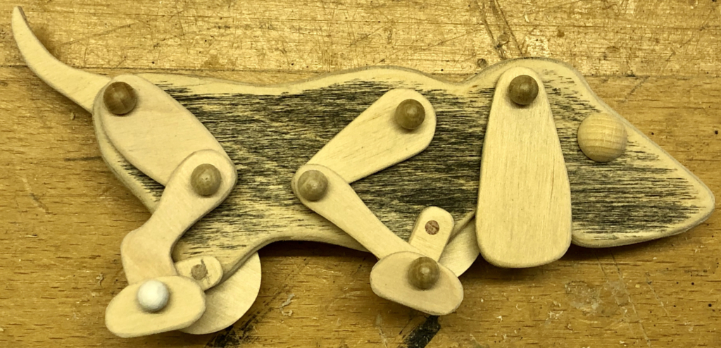
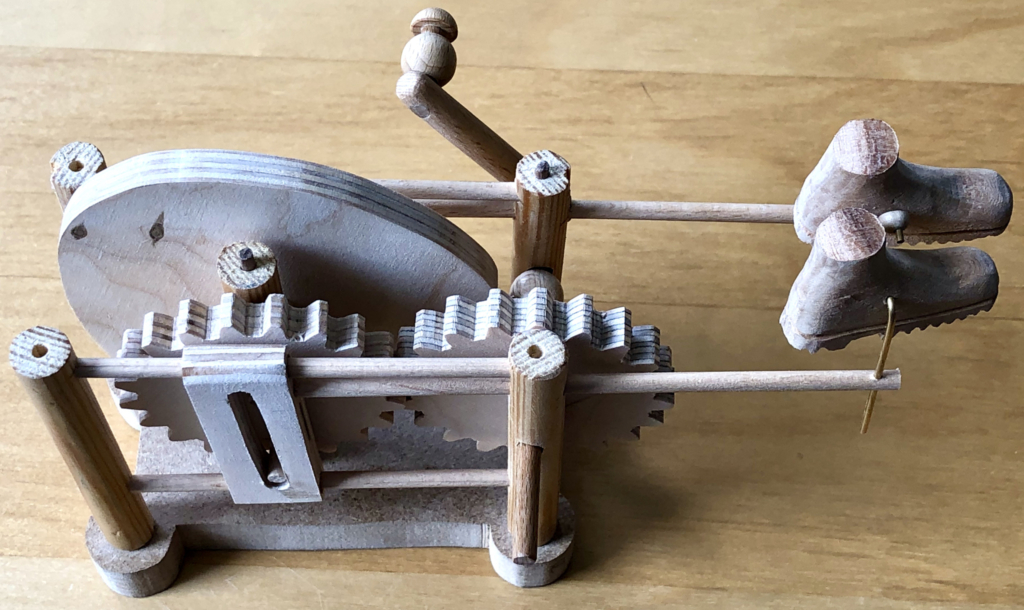
With judicious use of 3 mm dowel and some 6 mm hemispheres to cap the ends, the assembled dog looks something like this.
The base
My original design for the base shows two identical cogs, each with 20 teeth. I used https://woodgears.ca/gear_cutting/template.html to produce and print their design, I glued them onto some 10 mm plywood and cut them out. But why, did I need cogs at all? As the slotted mechanism to move the boots, slides back and forth in front of the cam, it is not possible to simply extend the cam’s centre axle and fit a crank handle to its end. My solution to this problem is to use two cogs to effectively move the drive axis outside of the cam.
This is easier to understand from a picture taken from above the mechanism.
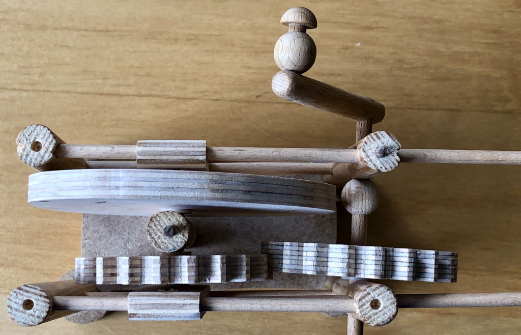
Here you can see 5 pillars made from 12 mm dowel. There is one pillar at each corner and one towards the centre. This centre pillar holds the short axle which joins the cam to the left-hand cog. As the crank is turned, it turns the right-hand cog which in turn drives the left-hand cog, making the cam rotate.
The left-hand cog also has a pin in its outer face to drive the second slide
As the cog is turned, its pin then moves the slide backwards and forwards, thus moving the boot.
The hinge
So far there is no connection between the dog and the base so we need a hinge.
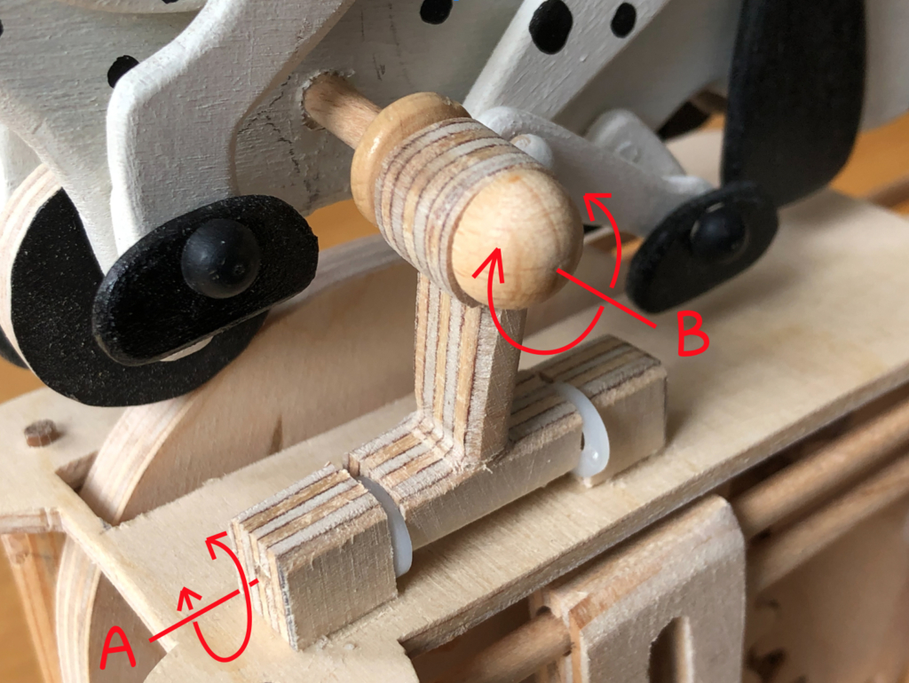
A piece of 4 mm dowel is fixed to part of the dog’s body where the moving legs can’t bump into it. This dowel can turn around axis B allowing the dog to tilt gently forward and back as the irregular cam turns. To make sure that both wheels stay in contact with the cam, rotation around axis A allows the dogs whole body to move gently up and down. This all means that the dog’s movement is more lively and interesting as it tracks the profile of the rotating cam. I chose not to restrict the rotation around axis A which means that the dog can swing wildly if you pick up the finished thing too impetuously. This may be a problem with children, but I’m sure adults will be more cautious. My dog did tend to loose contact with its rear wheel so I added a weight inside the body, above the rear wheel which fixed that problem nicely.
Left-handed
I didn’t intend to make it suitable for left-handed use, but that’s how it turned out. With the boots at the left-hand side you naturally want to hold the base with your right hand and then turn the crank with your left hand. I thought about putting the crank on the other side to make it right-handed, but then you would be looking at the side with the hinge and I preferred to avoid that.
Lucky lefties! But hey why ever not? When I build something for the first time I find that I can never think of everything in advance. My brain starts to hurt. After my day’s ration of decisions has been used up, I just wait with interest to see how things turn out.
Video – In Dogged Pursuit
Link https://www.youtube.com/watch?v=2i5Feok_heI
Images
Download here https://www.wordwise.de/In_dogged_pursuit_images.zip