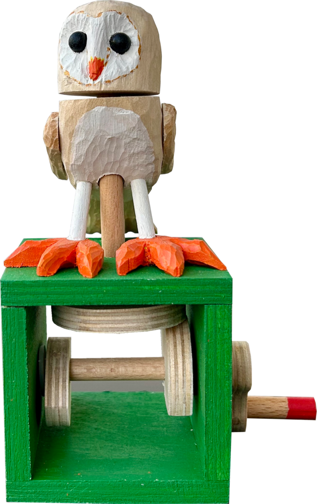
My small friend’s birthday was due and I thought it about time to make her a simple automaton of her own. There is an owl on her school rucksack so I decided to make an owl for her desk. Owls are famous for being able to turn their heads through a wide range, which meant that I didn’t have to think too long about the required movement. I found a couple of nice examples on the Internet, two from Carlos Zapata (one older http://carloszapataautomata.blogspot.com/2012/01/small-barn-owl.html and one newer https://www.youtube.com/watch?v=dcnn2QUscbY&t=20s) and one from Paul Spooner (https://cabaret.co.uk/product/the-owl-and-the-pussycat-by-paul-spooner/). This owl is not disagreeing with anything in particular, it’s just keeping its eyes peeled for any juicy mice in the vicinity.
Design Constraints
Intended for an eight-year-old, it has to be safe, robust and easy to operate. That’s why I rejected brass rods in favour of chunky wooden dowel. It is also why I broke a habit and didn’t put a red ball on the end of the crank handle, just painting it red instead.
Making the Owl
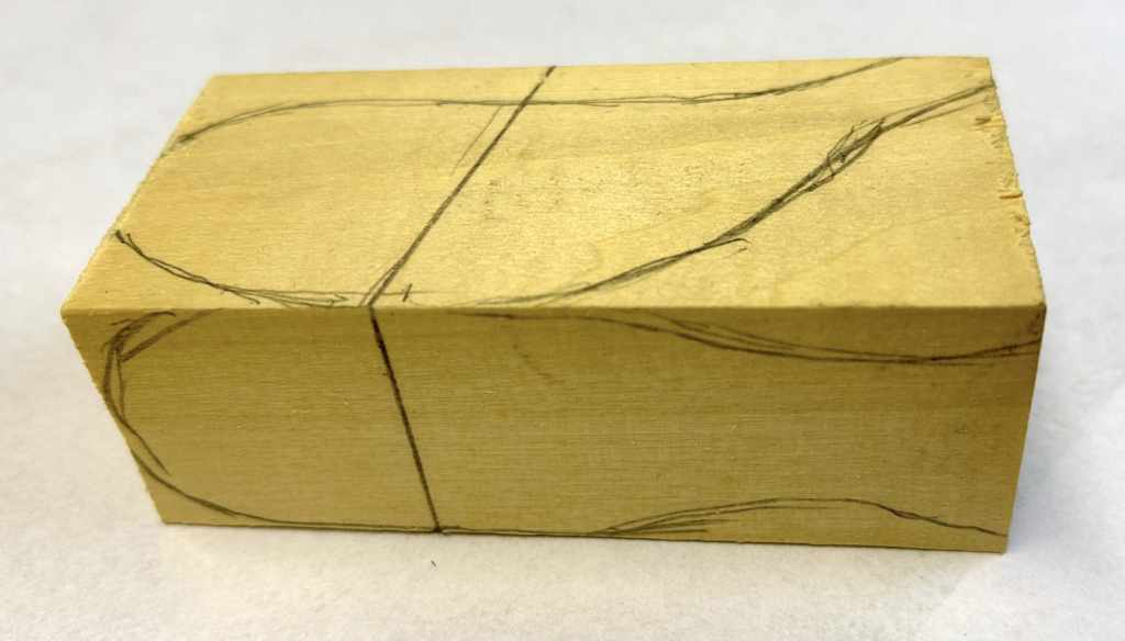
After making a model owl in plasticine, for the body I chose a suitably sized piece of limewood and marked the outline onto two sides. As the owl’s body leans forward, the cut between the head and the body has to be tilted so that it will be horizontal when the body is held in its tilted position by the legs.
A scroll saw will cut out the basic shape.
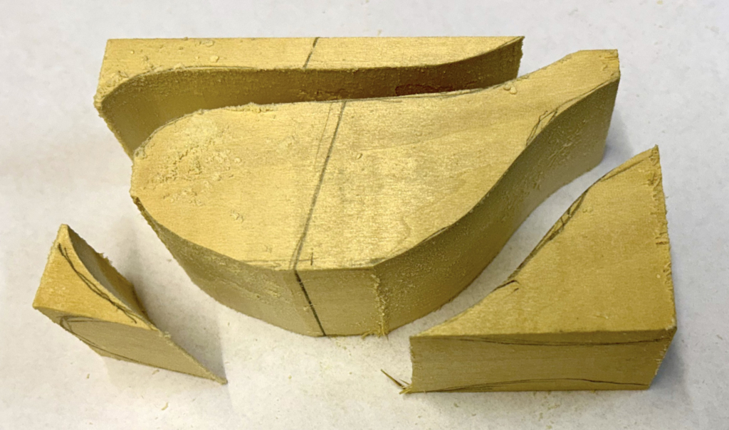
As you can see, the first set of cuts remove the side markings, so you have to redraw them on the surfaces which are now curved.
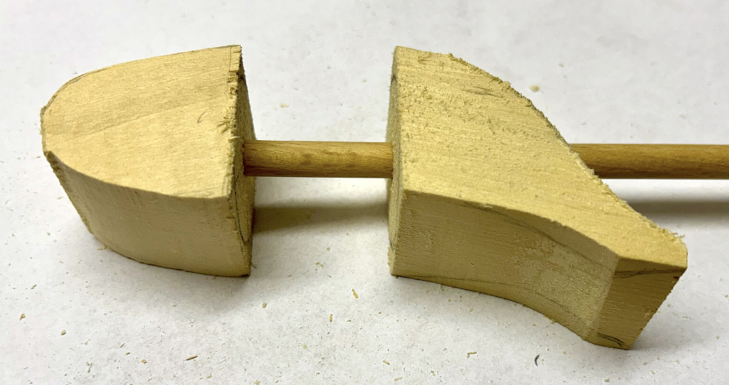
For the shaft which turns the head, It is a good idea to drill the holes while two faces of the body are still parallel to one another, that means before making the second set of cuts along the markings which you had to redraw on the curved surfaces.
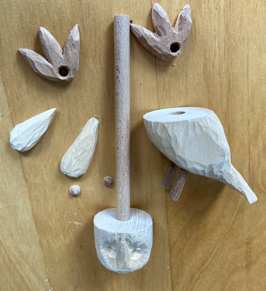
When carving, the bottom of the head and the top the body must be cut to a circle with the same radius so that, as the head is turned, nothing protrudes outside of the body.
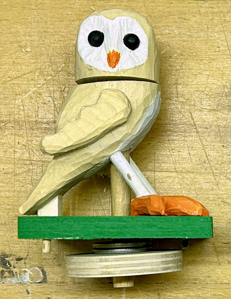
An 8 mm diameter dowel is fixed to the head and passes freely through 8.5 mm holes in the body and the top of the base box to the drive wheel fixed to the bottom of the dowel. A couple of chunky steel washers increase the weight, pushing the drive wheel more firmly down onto the two cams.
Making the camshaft
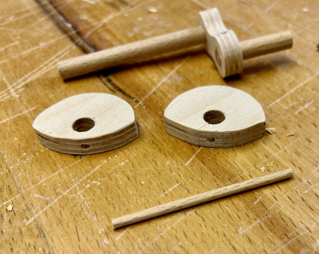
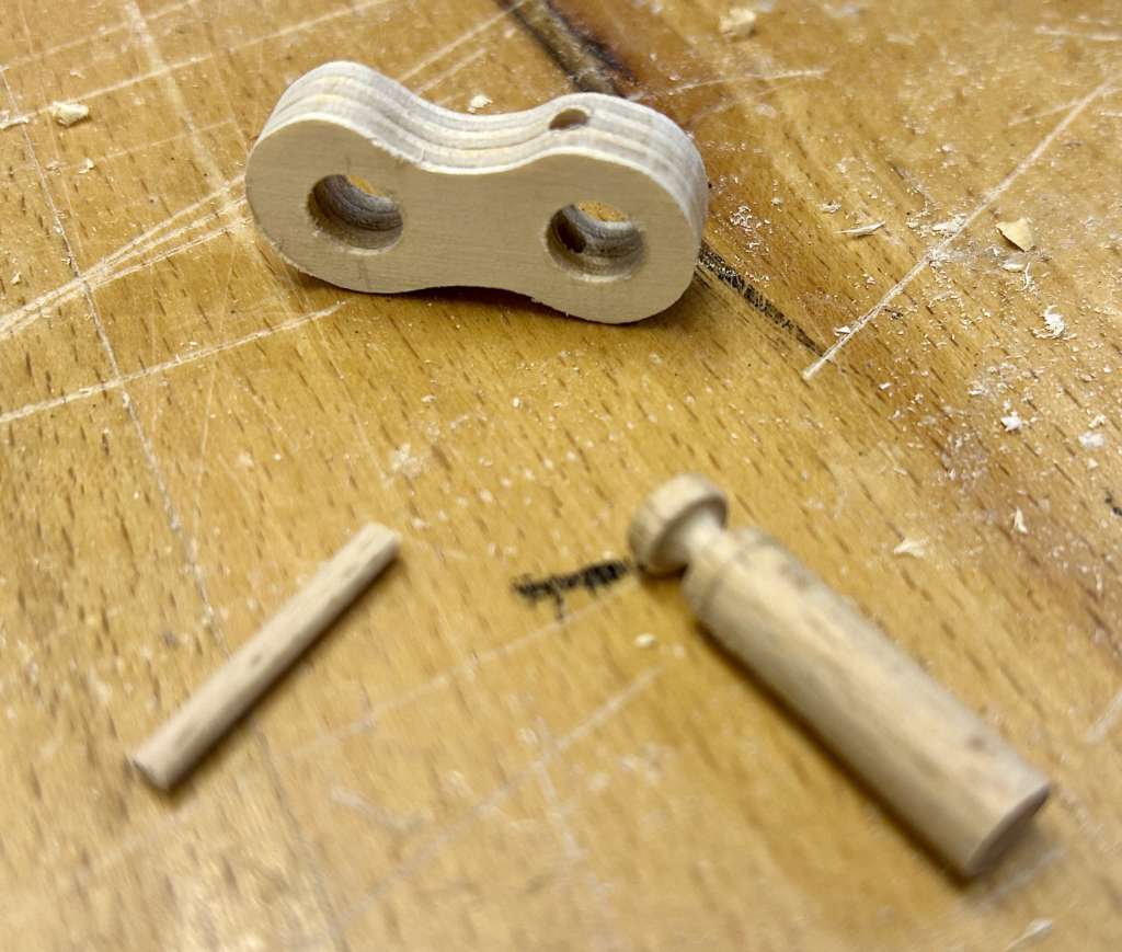
I used 8 mm dowel for the camshaft and the handle to crank it. The two cams mounted onto the shaft are identical, taking turns to move the drive wheel via friction. Either one or the other of them is always in contact with the drive wheel so that the owl’s head stays more or less at a constant height, just rotating – first one way and then the other. A small piece of 3 mm dowel pins each cam onto the camshaft.
To keep it simple, I placed the cams close to the side of the base, just separated from the walls by nylon washers, ensuring ease of movement.
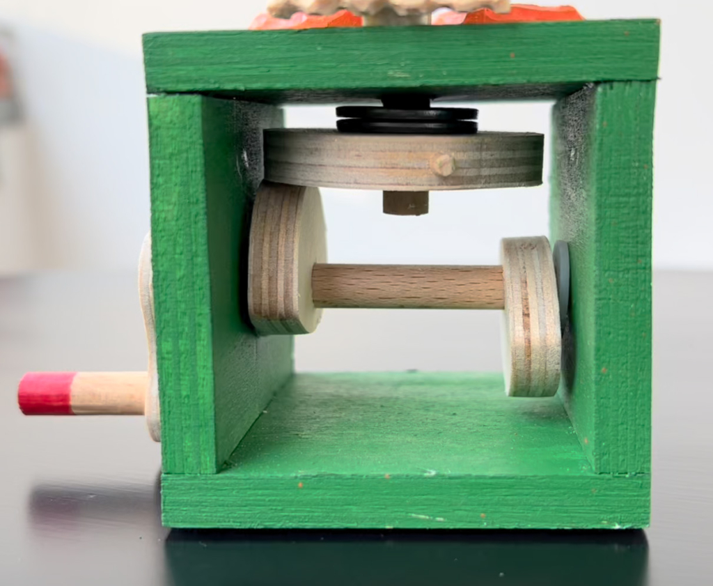
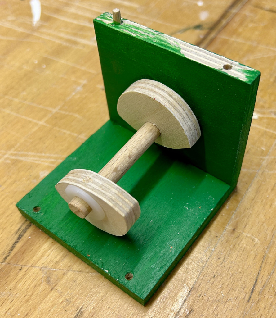
Looking at the base, you can see that the cams rub against the outer edge of the drive wheel. The transmission ratio here is about 1 to 1 so that the owl’s head turns by about 180° before it changes direction. If the cams were positioned closer to the centre, it would be possible for the head to turn by more than 180°. Owls can apparently turn their heads through 270 degrees, but I was happy with about half a turn, limited by a 3 mm dowel pin inserted into the outer edge of the drive wheel. When this pin touches either side of the base, it prevents further rotation.
Making the Handle
In the past, I have put a ball on the end of the handle and arranged for it to slip freely when rotated. This time I thought “forget the ball” and make the handle itself slip freely. Both ideas mean that you do not have to let the handle slip through your fingers as you turn it. It’s a small thing but it does make things a bit easier to use.
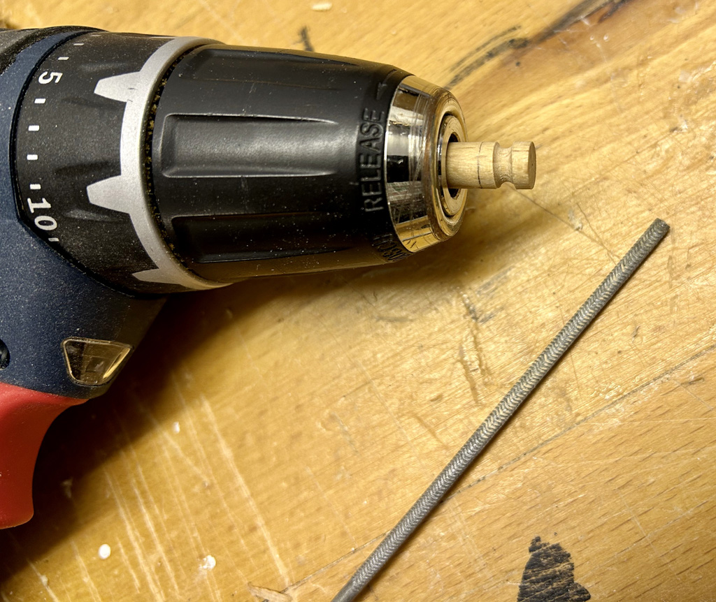
I don’t have a lathe, so I used my hand-held battery-powered drill to rotate the 8 mm diameter handle and a small round file to add a groove near to the end. A piece of 3 mm dowel inserted into the crank prevents the handle from being pulled out, while allowing it to turn freely.
Thoughts on Friction
Relying on friction between the cams and the drive wheel means that no toothed cogwheels are required. It also means that small hands can grab the owl’s head and turn it without any damage occurring. The drawback is that friction also occurs everywhere that a moving part is in contact with a still part such as where the dowel linking the drive wheel to the owl’s head passes through the base and through the owl’s body. These points are essentially the bearings needed to keep the dowel properly aligned. If the bearings are too loose, the dowel and thus the drive wheel will tilt and not turn so easily. If the bearings are too tight, the dowel will be stiff and may not turn when required.
My pragmatic approach is to start with tight holes for bearings, enlarging them as required when tests show that the movement is too stiff. For instance, for my 8 mm diameter dowel I first drilled 8.5 mm holes for the bearings, enlarging one of them to 9 mm after trying out the mechanism. Increasing the weight via washers increases the friction where it is wanted, between the cams and the drive wheel.
Video
Images
Download images from https://www.wordwise.de/Archive_of_owl_images.zip