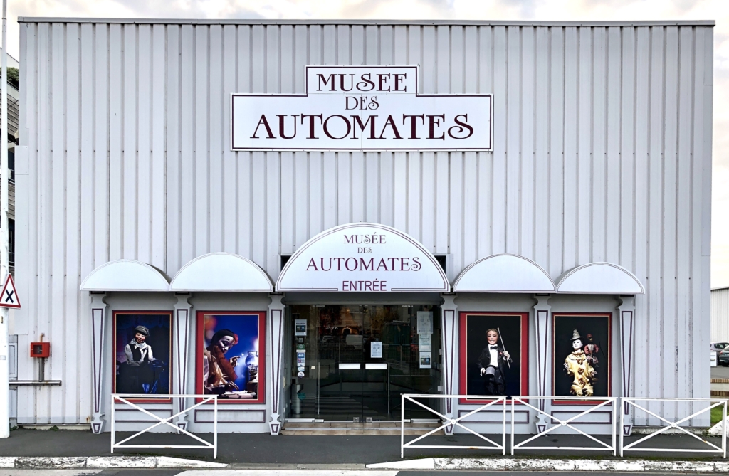
In 2021, I visited La Rochelle, an attractive seaside town on the Bay of Biscay in France. After a delicious lunch in one of the waterside restaurants, I popped into the Musée des Automates & Modèles Réduits (Museum of Automata and Scale Models – https://museeslarochelle.com) to take a look at their collection.
This museum opened to the public in 1984, with more than 30 years of work by the museum’s original creator, Michel Gaillard, to build up this collection. In addition to some prestigious antique pieces (for example made by Jouets et Automates Français (JAF), or Decamps …), there are some large animated displays. There are apparently more than 300 moving figures: mostly antique, with some animated window displays and historical scenes. I thought that I would share just a few impressions of what’s on offer.
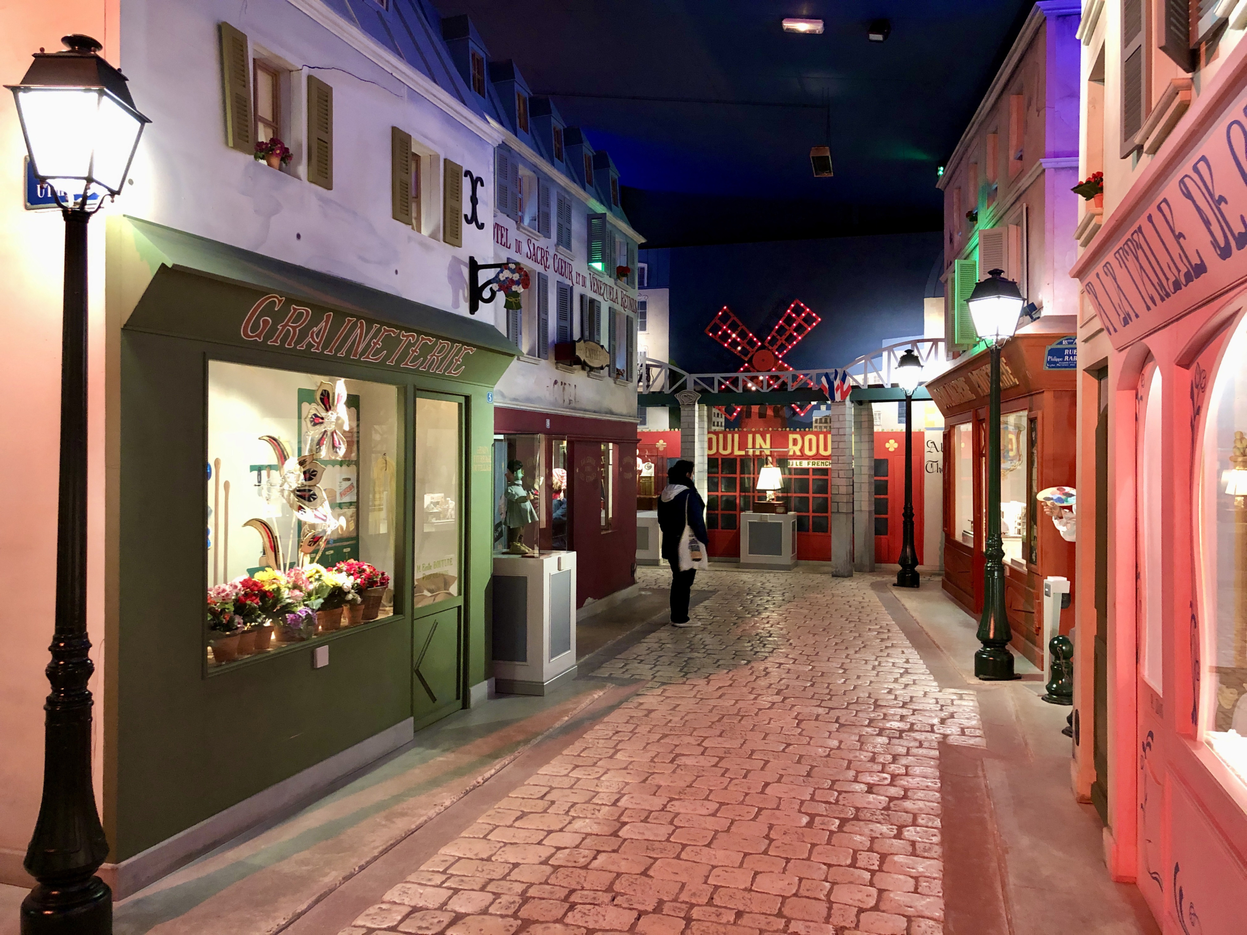
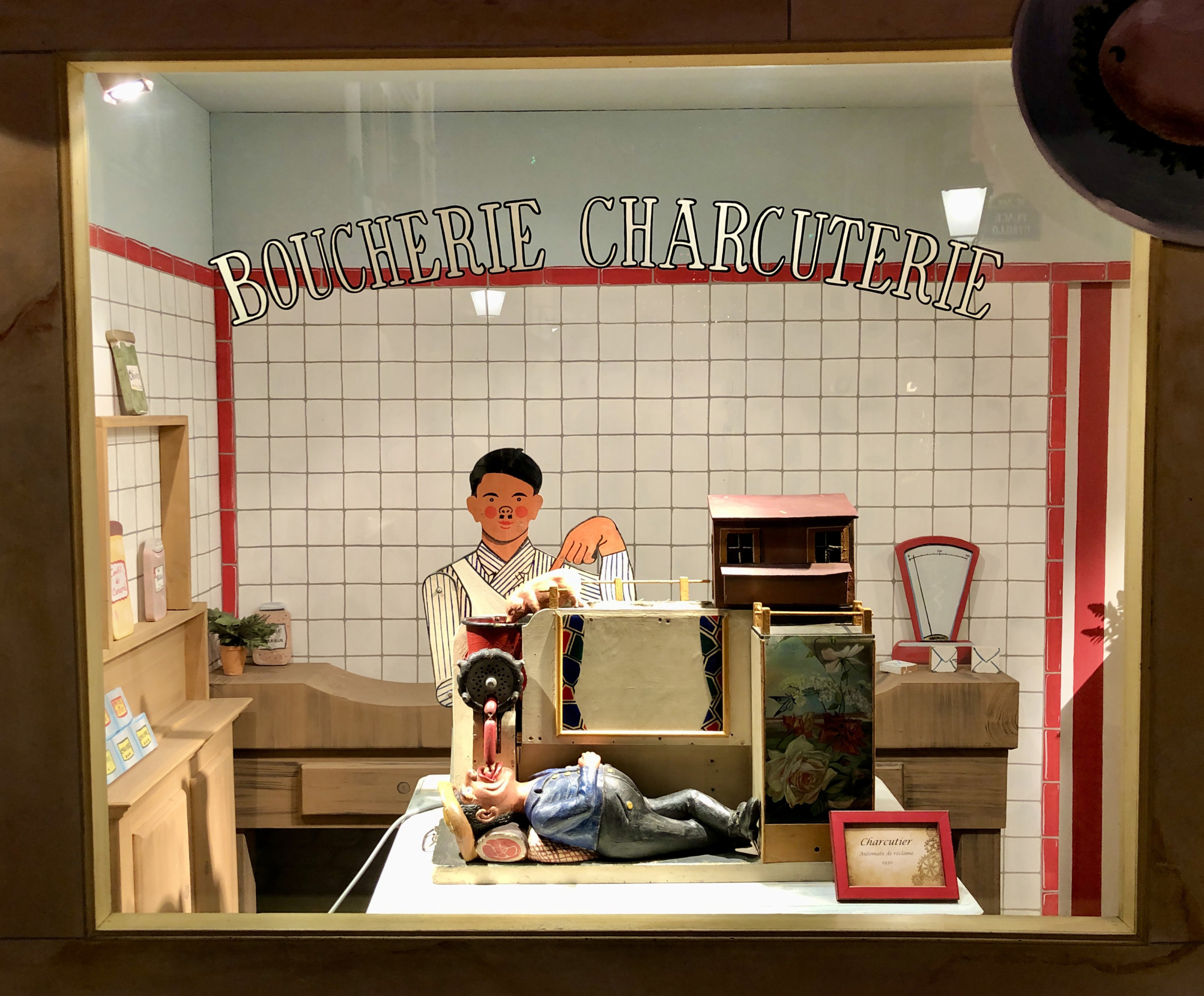
Here is part of a reconstruction of the “Montmartre” district of Paris, which is used as a setting for some of the automata from the first part of the 20th century.
Montmartre street sceneA butcher’s shop
One of the shop windows shows a French butcher’s shop, with an automaton which I guess was used for advertising in the days before television took over the job. It reminded me of a modern work by Paul Spooner “Little Reinhold’s Wonderful Sausage Machine”.
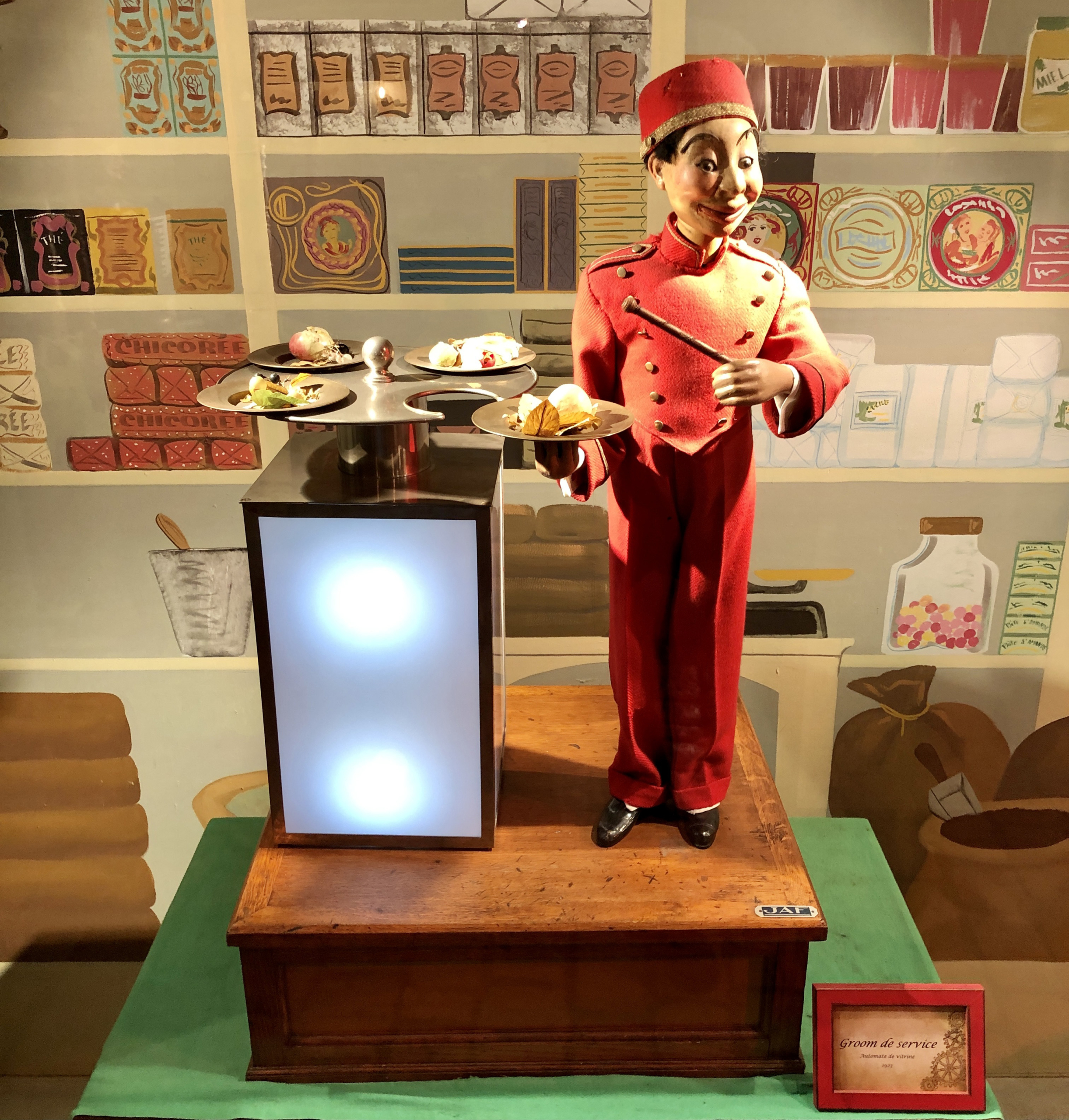
“Groom de service” 1923
It’s fun to speculate what this piece “Groom de service” made by JAF in 1923 was used for. I imagined it on the counter of a bar serving plates of salted snacks to keep the customers thirsty.
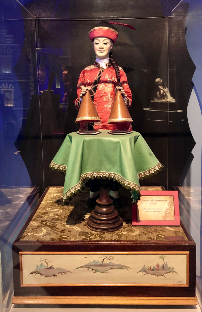
Le Jouer de Bonneteau
Of course there was a magician.
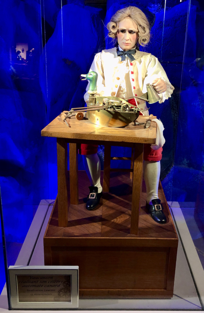
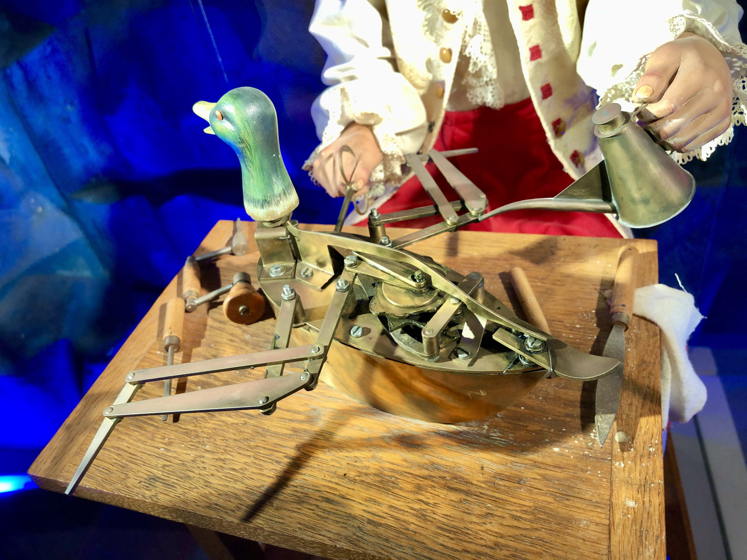
The caption reads “Vauconson réalisant son célèbre automate canard. Réalisation Laurent 13 mouvements”
This work made me wonder a bit. It’s an automaton showing an automaton-maker at work. Its title loosely translates as “Vauconson making his famous mechanical duck. I took a quick peek in Wikipedia to find an article in French about a digesting or defecating automaton duck, created by Jacques de Vaucanson around 1734.
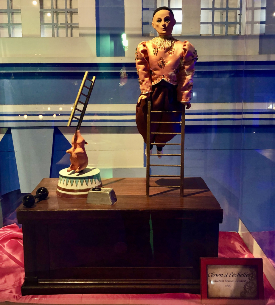
A classic automaton showing a clown balancing on a ladder, made in 1895
This clown balancing on a ladder together with a pig balancing a ladder on its nose, was made in 1895 by another famous automatist called Leopold Lambert. Follow this link https://mus-col.com/en/the-authors/10280/ for a short biography.
It was an interesting visit for me even though I know nothing about antique automata. The entrance fee also includes a visit to the adjacent museum which has a collection of model ships and a model railway setup.
The museum is within walking distance of La Rochelle town centre at 12-14 rue de la Désirée, 17000 La Rochelle
Other Automata Museums in France
If you search for “musée des automates”, you will find several matches in France.
I recently watched a friend brush her daughter’s teeth before putting her to bed and I wondered how rabbits set about this mundane task. I mean they have very visible teeth which they must be quite proud of and they can’t pop around to the shops to buy a toothbrush. I have never asked a rabbit, but I am guessing that they might use a bit of brushwood as they live a healthy outdoor life.
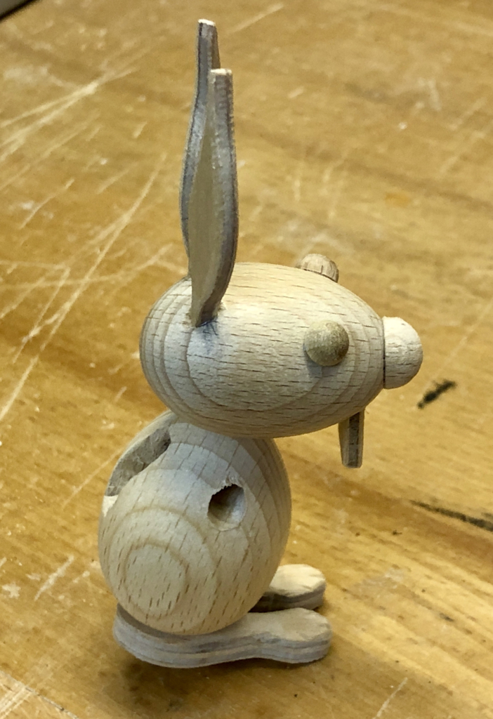
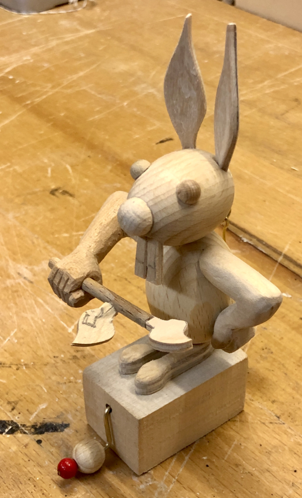
The rabbit
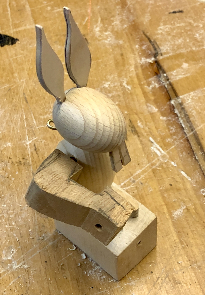
Two wooden eggs basically make up the rabbit’s body and its head. 3 mm plywood serves to make the teeth and ears. A piece of 5 mm dowel joins the rabbit’s head to its body.
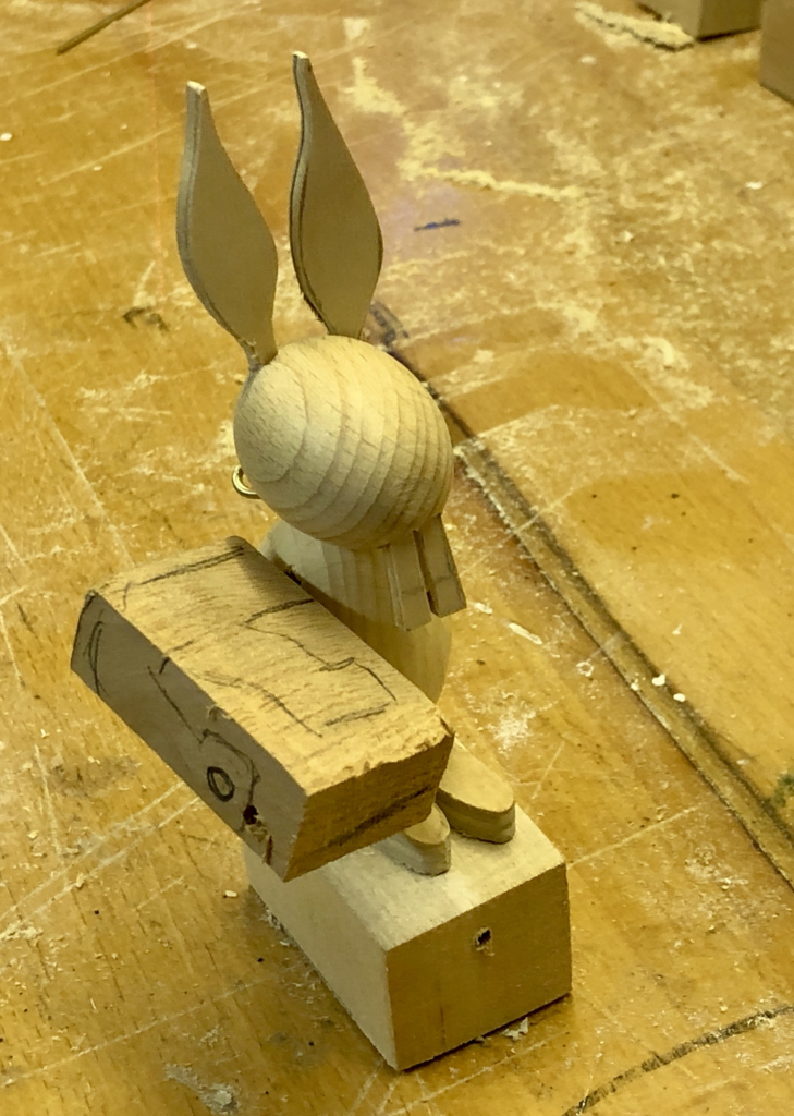
A through hole, drilled sideways through the body, loosely accommodates a piece of 4 mm dowel to which the rabbit’s right arm will be attached. A slot cut in the rabbit’s back allows a brass lever to be inserted into the dowel to rotate it a little.
The angle of the arm to the body is important if our brushwood brush is to move correctly in front of the teeth so, before doing any carving, I checked that the angles were correct with a very rough arm.
Once the angles are OK, it’s safe to cut the arm roughly to shape before starting to carve.
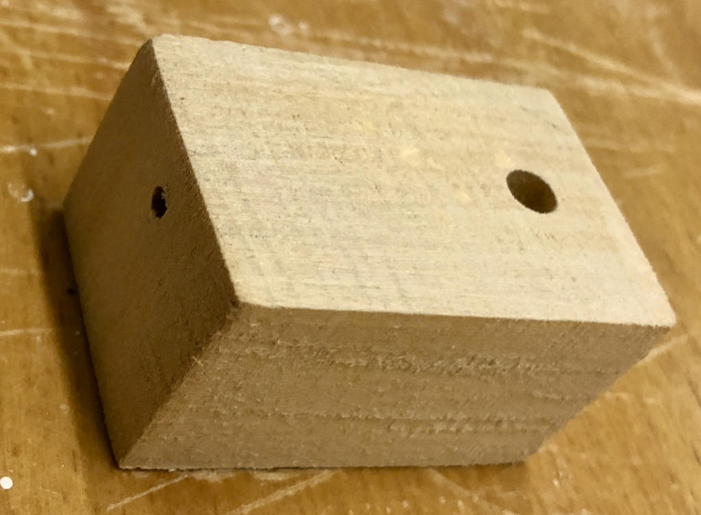
The base is a simple rectangular block with a through hole from front to back for the crank to turn easily and a hole for some dowel to attach the rabbit to its base.
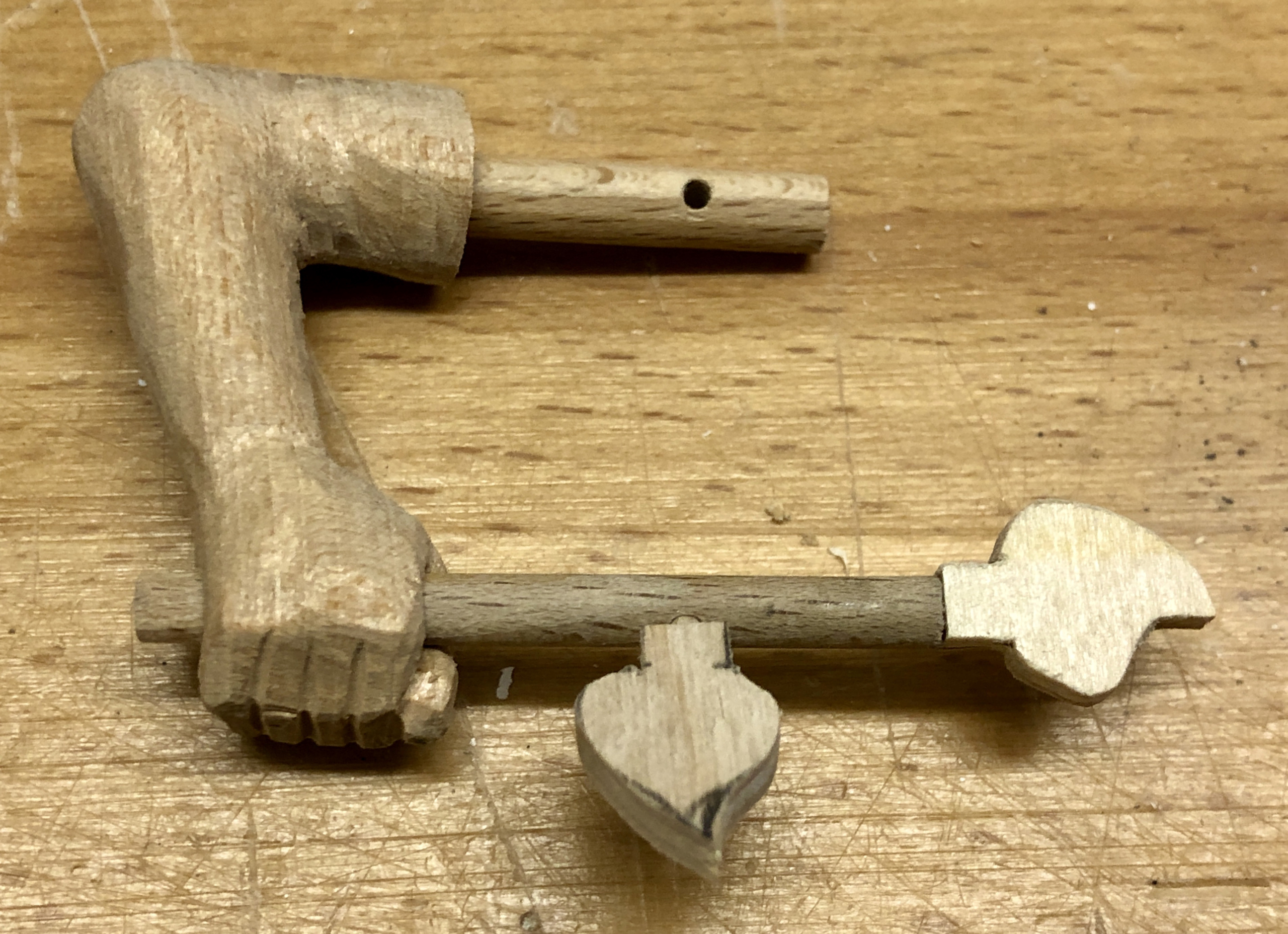
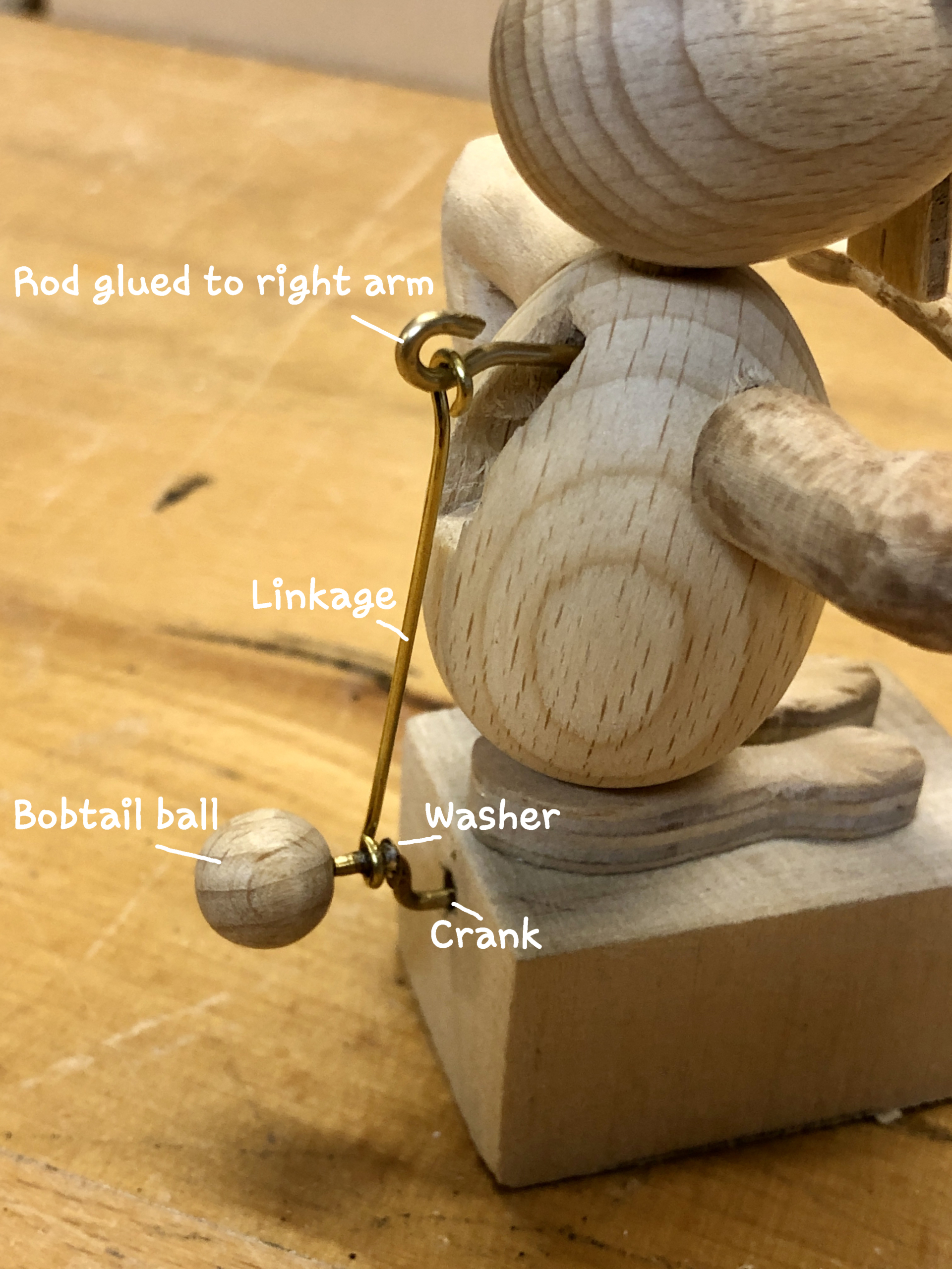
Once the rabbit was largely assembled I glued a piece of brass rod into the horizontal dowel to move the rabbit’s right arm up and down. Another piece of brass rod passes through the base and I bent this into a crank. When the crank is at the top of its movement, the arm is down, when the crank is at the bottom of its movement, the arm is up. A certain amount of experimentation is needed to get the crank dimensions just right.
If you look closely, you can see that I soldered a small washer onto the crank to keep the vertical linkage on the horizontal part of the crank and to prevent it from slipping down towards the base. A wooden ball glued in place prevents the linkage from slipping off backwards, away from the base. When painted white this suggests a bobtail for our rabbit.
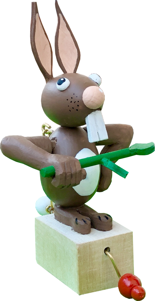
The front part of the crank has two balls, a small one which is glued in place to retain the larger, free-turning ball. Grabbing this larger ball allows you to rotate the crank endlessly, without having to let go. The rabbit’s left arm doesn’t move and is glued in place, covering up the end of the hole containing the horizontal dowel. The toothbrush is a piece of dowel with two token leaves attached. This rabbit has long, rabbity feet but its legs are left to your imagination as an unnecessary complication.
Final thoughts
The finished bunny is quite small, about 13 cm high and its mechanism is extremely easy to operate. Some of my larger creations can be quite stiff to use, especially for children. It was fairly quick to make apart from the carving. I enjoy taking my time when carving, making hands with fingers and thumbs always takes a while (my rabbit has fairly human hands). With no explanation, adults find it hard to understand what is going on here. I considered writing the title “How do rabbits brush their teeth” on the side for English-speaking adults but have decided against it. Mysteries are an interesting part of life.
I was poking around a museum shop in Denmark and I came across a splendid elephant designed by Kay Bojesen and made of oak. There are images of this classic product on the Rosendahl web site. I thought that it would be fun to have a go at making my own elephant with some interesting movement. My elephant would have to be able to pick things up with its trunk and of course it would have to be able to fly. I did think about Dumbo-style ears but on consideration I thought that was a bit far fetched. How can an elephant possibly fly by flapping its ears? Instead of that, my elephant has a very modern howdah strapped to its back which contains the mechanism to drive a high efficiency helicopter-like propeller. As usual, there is a crank protruding from the back of the howdah to get things moving.
Technical Requirements
The trunk should be rigid, operated by unkindly pulling our poor elephant’s tail. To help her to pick things up a magnet is required in the end of her trunk. The propellor should be friction driven to make it less likely that over enthusiastic admirers can break parts such as a pin wheel. This friction drive should work even if the elephant is up side down. We don’t want to risk a dangerous power loss during aerobatic manoeuvres.
Making the Elephant
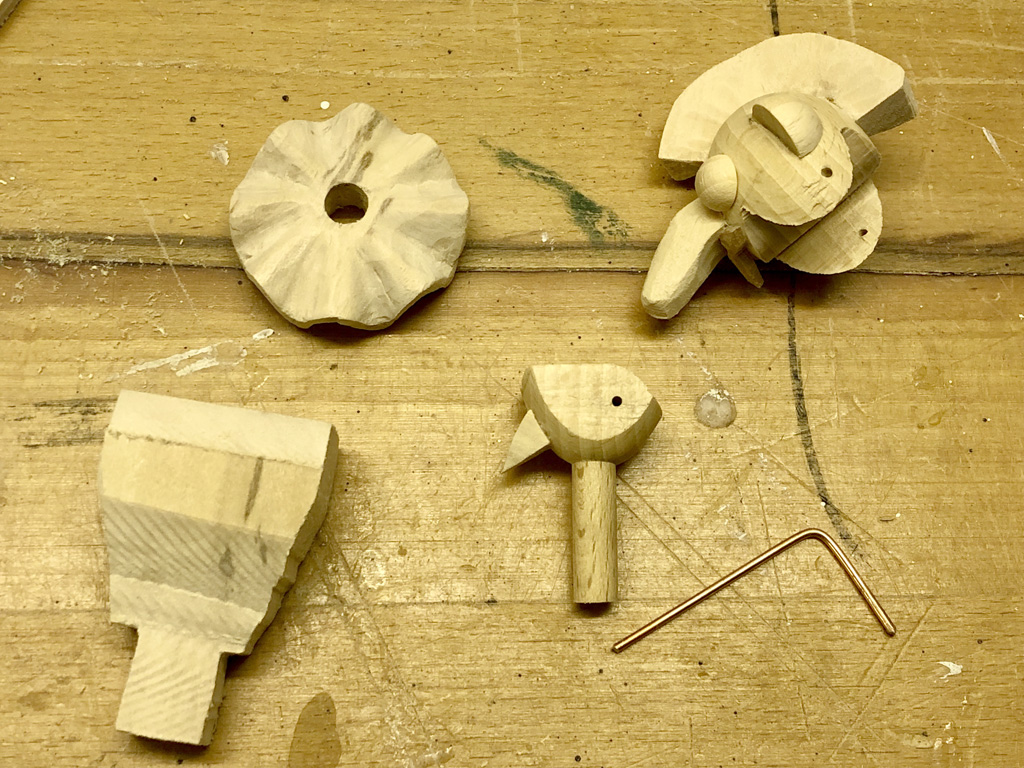
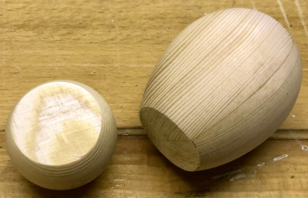
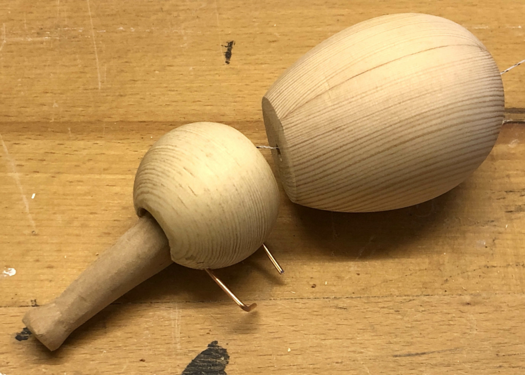
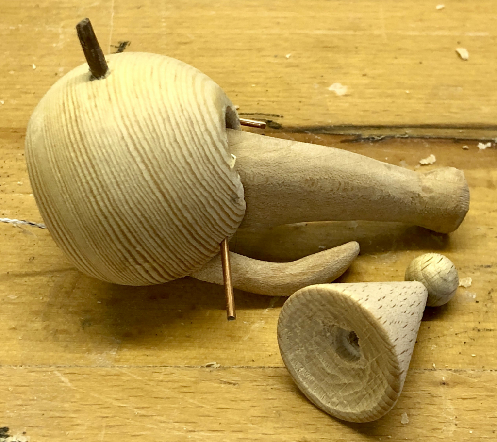
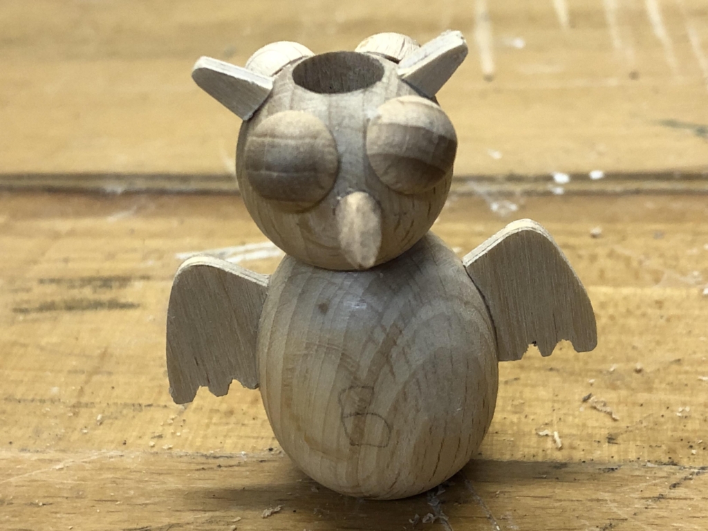
The head is made from a wooden ball and the body from a wooden egg. Cutting a slice off of each part makes them fit nicely together.
Head and body
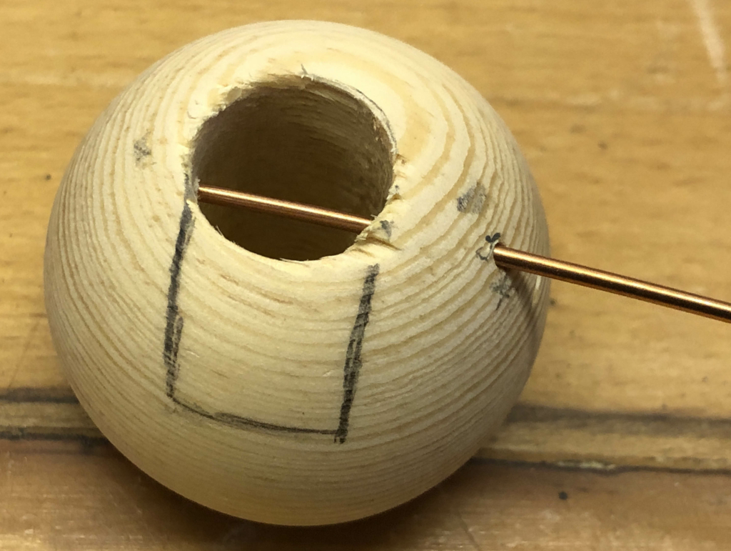
A hole drilled through the head is as wide as the elephant’s trunk allows a string to pass through. A slim brass rod serves as a hinge for the trunk.
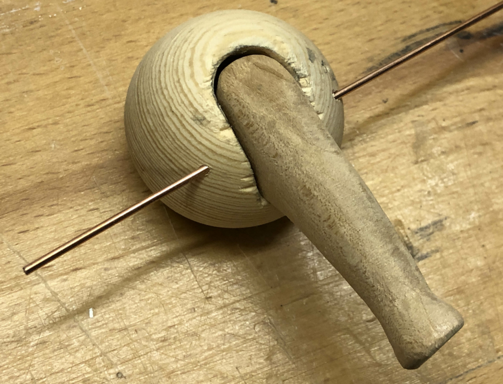
The trunk is carved from a piece of lime wood with a suitably drilled hole for the brass hinge rod.
The trunk hinged in the head
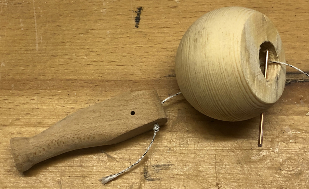
The string emerges from the top of the trunk and another brass rod, near the bottom of the opening, makes sure that tugging the string results in a downward pull to make the trunk lift up.
The string to pull the elephant’s trunk up
A hole drilled straight through the elephant’s body allows the string to come out where the elephant’s tail will be.
Now we have to carve a pair of tusks and make a hat from a wooden cone which sits at a jaunty angle.
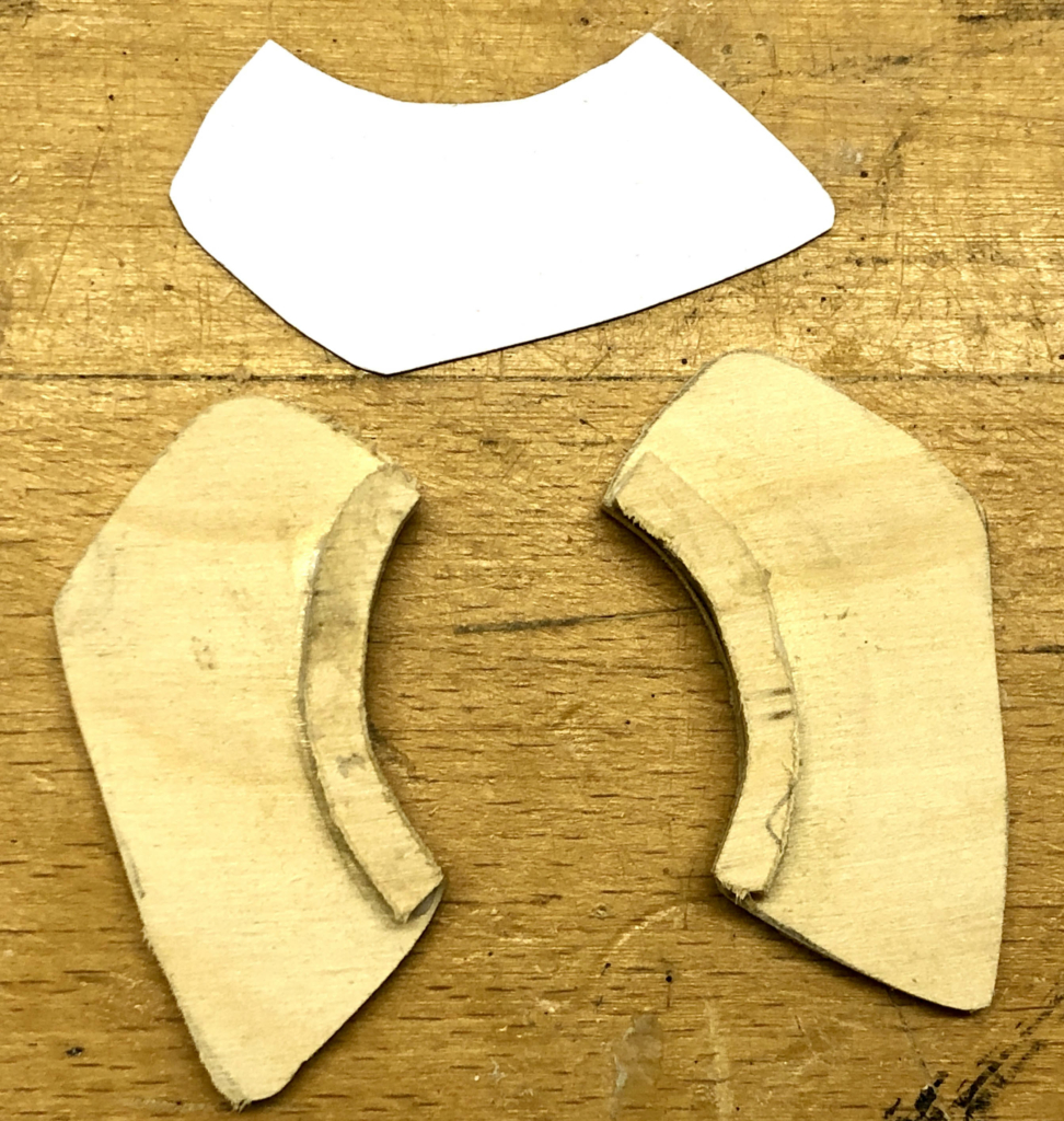
Use a template to cut two ears from 3 mm plywood, adding a slim strip of the same material to strengthen the simple glued bond to the head.
Two ears
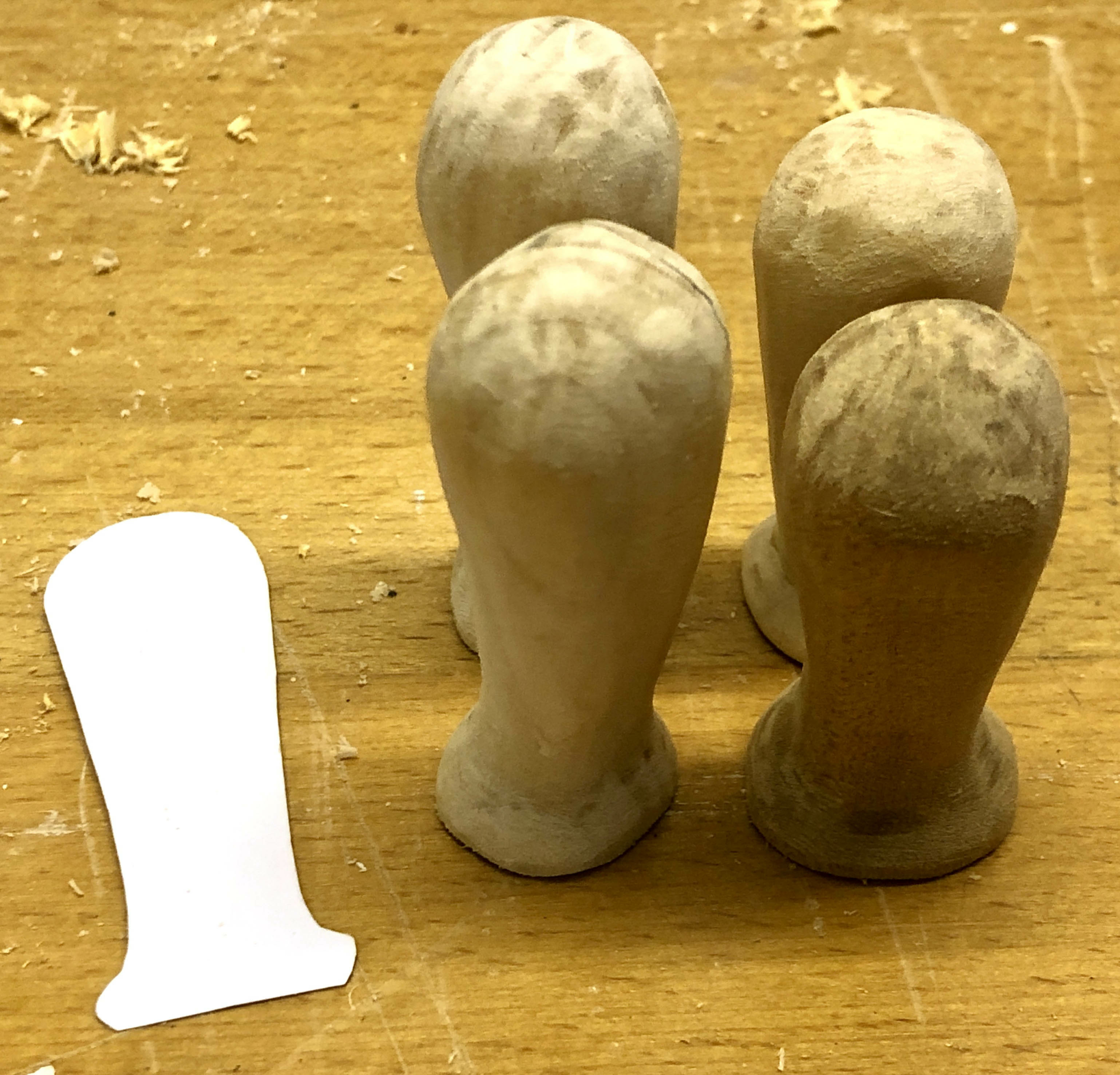
Now we have to carve four legs, two longer ones at the front and the shorter ones at the back.
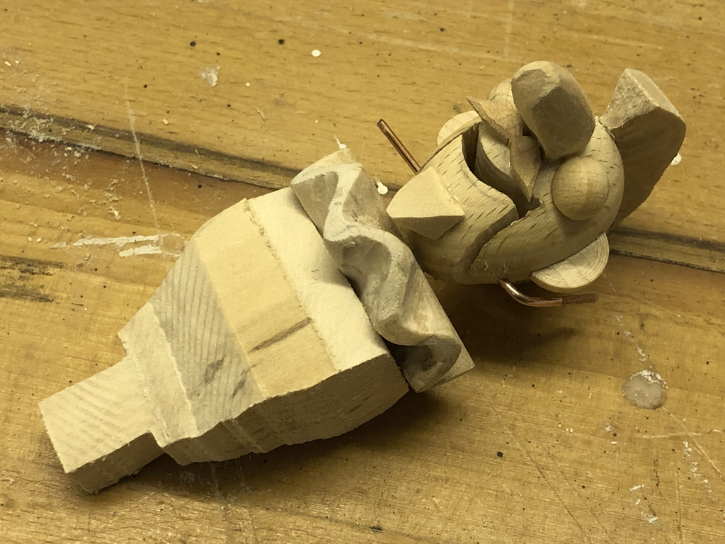
Four carved legsThe elephant without her howdah
Adjusting the legs to fit against a slightly tilted egg shape was a bit tricky. Trial and error got me there in the end.
Tip
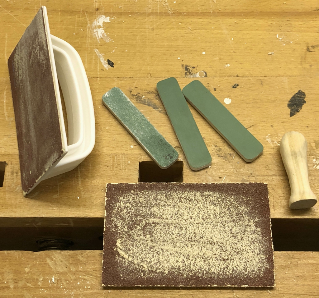
Sanding tools
I don’t have a sanding machine as I find the “tools” in the picture do the job for me. The larger tools have a velcro pad to hold suitable sanding papers which you can either use free hand or they can be clamped in a vice. The smaller ones are pieces of fairly rigid foam with pieces of sandpaper glued to the surface. Available in a variety of grades, these are great for smoothing elephant legs.
Making the howdah
Usually howdahs were put on elephants so that wealthy princes could ride around in style or in older, more disreputable, times go tiger hunting from a safe height. My howdah contains the mechanism to allow our pink elephant to fly around.
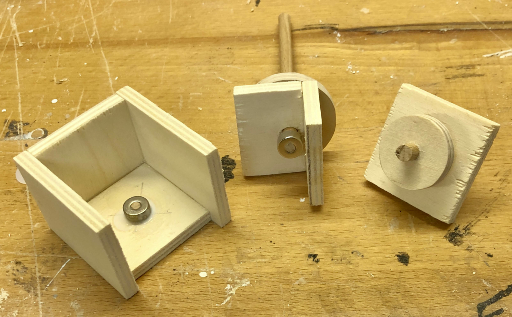
Howdah parts ready for assembly
In the picture you can see three parts. The left hand part is the basic box with a small magnet glued in the bottom centre. The right hand part completes the box and carries a plywood wheel which is turned by a crank outside of the box. The centre part drops into the top of the box so that its wheel rests on the edge of the wheel which is turned by the crank.
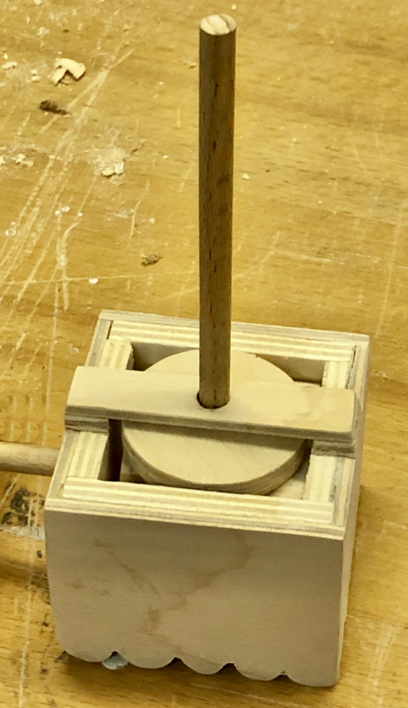
Howdah partially assembled
Note that the vertical dowel which will turn the “helicopter blades” also has a magnet on its lower end. This is attracted to the other magnet and has the effect of pulling the horizontal wheel down onto the vertical wheel which is turned by the crank. Without this gravity would do a similar job, but only when the elephant is standing on a horizontal surface. Turn the elephant upside down and gravity would pull the wheels apart. The magnets also result in a stronger force than gravity provides, so there is a more reliable connection between the two wheels, while still permitting slip if a child try to turn things directly.
Howdah fully assembled
A strip of 3 mm ply above the horizontal wheel keeps the vertical dowel nicely perpendicular to the howdah, which now has some decorative sides added.
Finishing Touches
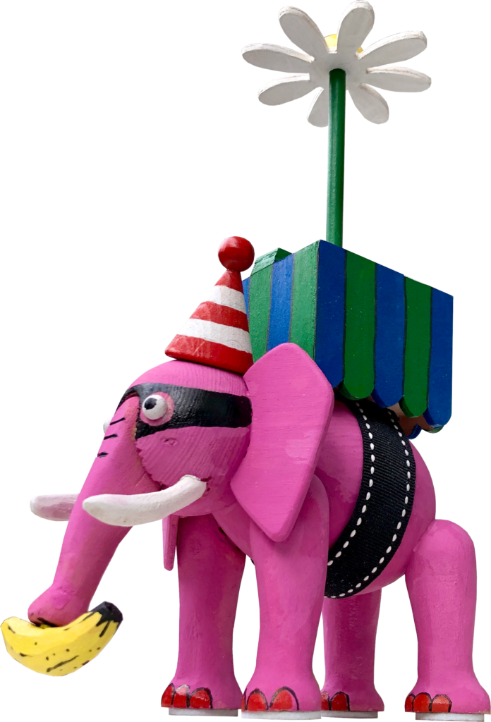
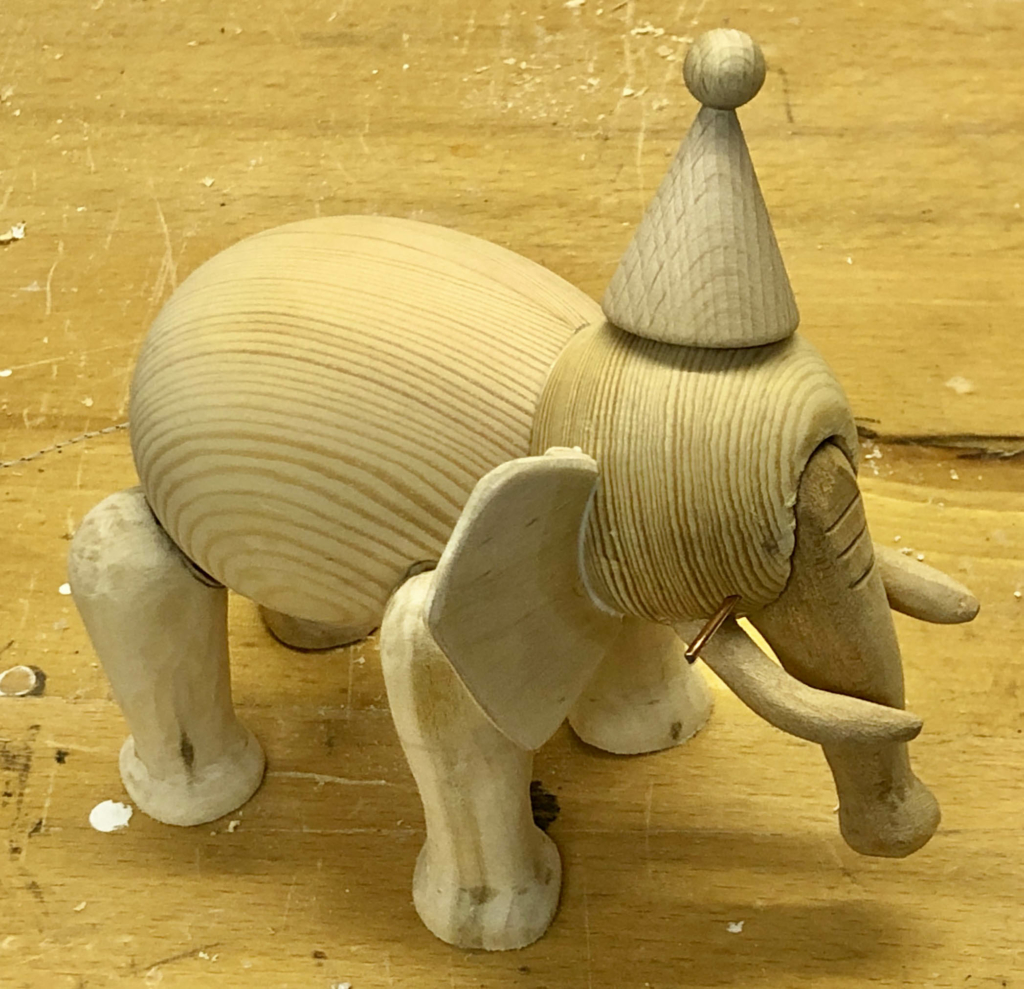
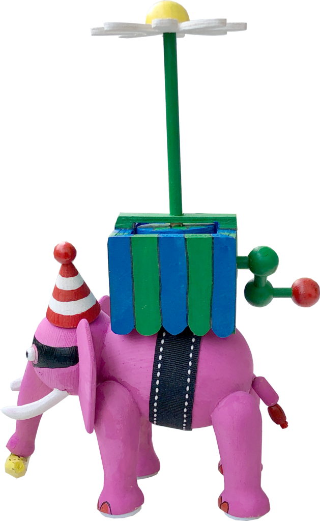
Finished pink elephant
I carved a small banana and added a few steel tacks to it so that the magnet in the elephant’s trunk can pick it up. Some tape from my wife’s sewing box served as the belt to apparently hold the howdah on the elephant’s back. Some 3 mm dowels and a spot of glue do the actual work of holding it in place. The tail is made of a couple of wooden beads. I painted a mask on its face remembering a joke that my father told me a long time ago about an elephant who robbed a jewellery shop and the red toenails must come from a childhood joke about elephants hiding in cherry trees. I was interested to read that elephants have a differing number of toenails on their front and rear feet. My helicopter blades look rather like a flower, so I added a few leaves to the horizontal wheel in the base to make it more realistic.
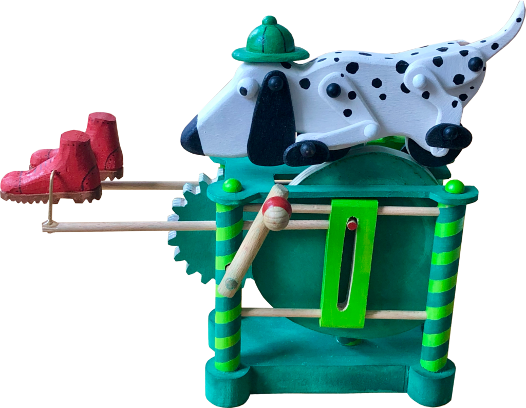
The other day I came across a picture of a vintage Fisher Price Snoopy Sniffer toy dog to pull along. Fuzzy childhood memories surfaced of having once seen one of these in action, with its doleful eyes and slightly frantic leg movement. Of course I couldn’t resist having a go at producing my own version, with a handle to crank so that I could admire it in one place on a convenient table, instead of having to scamper around with my nose to the floor risking a hay fever attack from low-level dust mites.
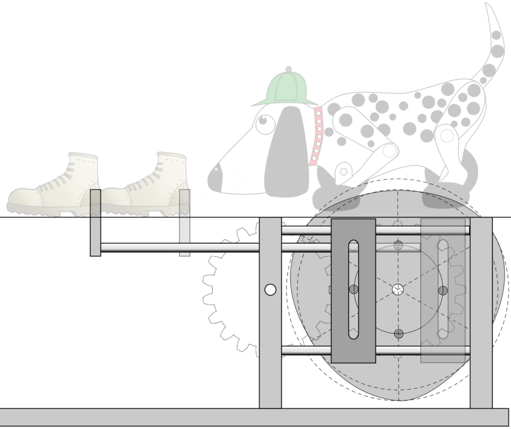
I had always thought of this as a bloodhound, probably used every day by Sherlock Holmes pursuing his Victorian Villains through the wild English countryside. A deer-stalker hat was thus indispensable! As far as a Victorian Villain was concerned, I thought I would take a minimalist approach and just show his boots. Maybe Sherlock is after the invisible man, who unfortunately has to wear sensible boots to carry out his villainous deeds?
To keep Sherlock’s Snooper Sniffing dog in one place, its wheels run along a rotating, slightly irregular cam, to make the movement uneven and so more interesting. As this cam turns, a pin protruding from its face drives a rod backwards and forwards to which a boot is attached. A realistic walking movement would see the boots not just move forwards and backwards, but also up and down. I’m afraid that my minimalist, invisible villain rather drags his feet and doesn’t lift them at all. I made the boots free swinging and, if you scrunch your eyes almost closed, you can imagine that it could actually be someone walking.
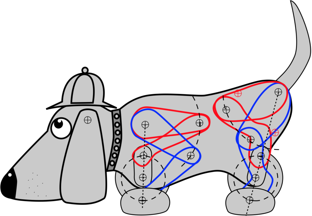
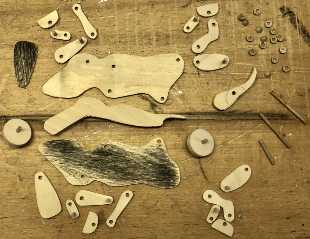
The dog’s design
A super sensitive nose close to the ground and an expressive tail are vital accoutrements for our canine sleuth. On a more practical level, its paws have to be moved in a circular motion via the wheel inside the dog’s body. As the paws move, the leg attached to the paw flexes and the elbow moves up and down, moving in an arc relative to the shoulder pivot. I drew the highest position in red and the lowest in blue. This was helpful to check that the front and rear legs don’t collide. When I was satisfied with that, it was then easy to dismantle the drawing to show the parts.
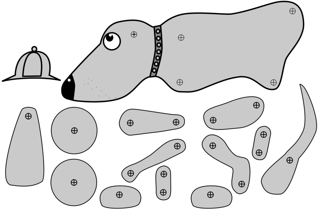
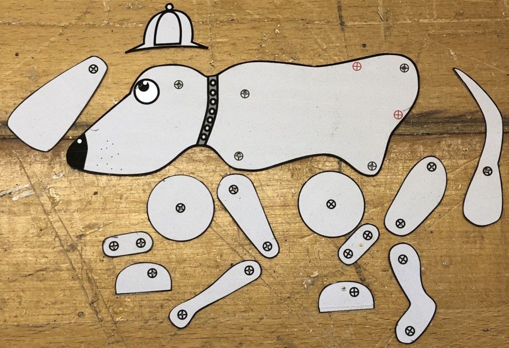
Printed out on some stiffish card, these can be cut out as templates.
Use the templates to mark some plywood, drill the holes and cut the pieces. One tail, four paws and two of everything else.
Most parts are in 3 mm plywood. The wheels are 6 mm plywood, so the two halves have to be kept 8 mm apart by a spacer which has the same shape as the top section of the sides. This also leaves space for the tail to swing around a bit.
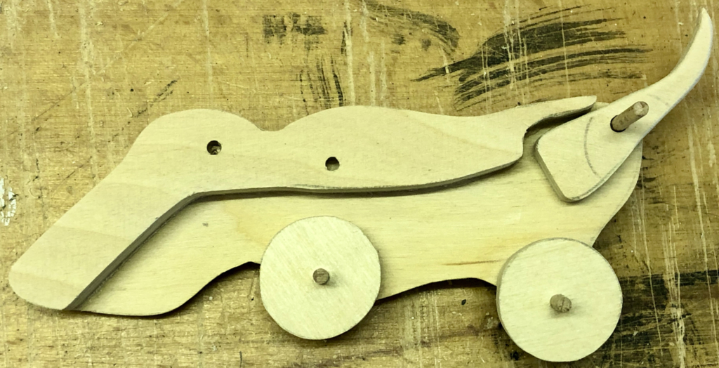
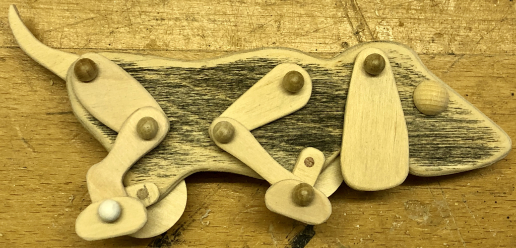
One side of dog with 8 mm spacer, two wheels and a tail.
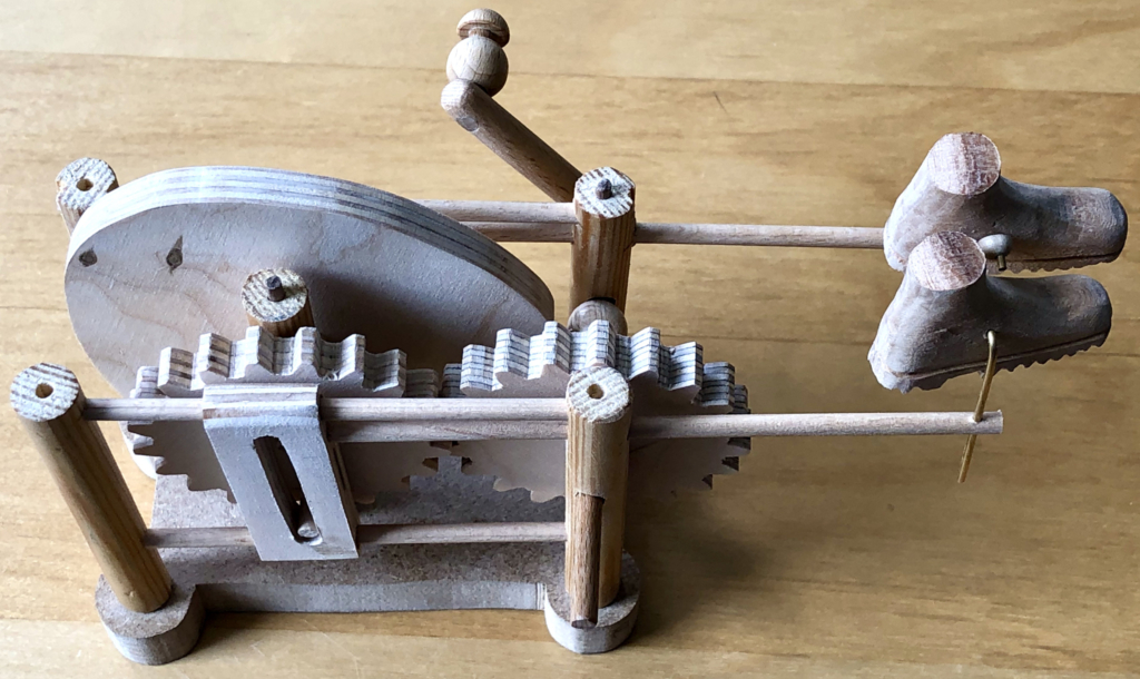
With judicious use of 3 mm dowel and some 6 mm hemispheres to cap the ends, the assembled dog looks something like this.
The base
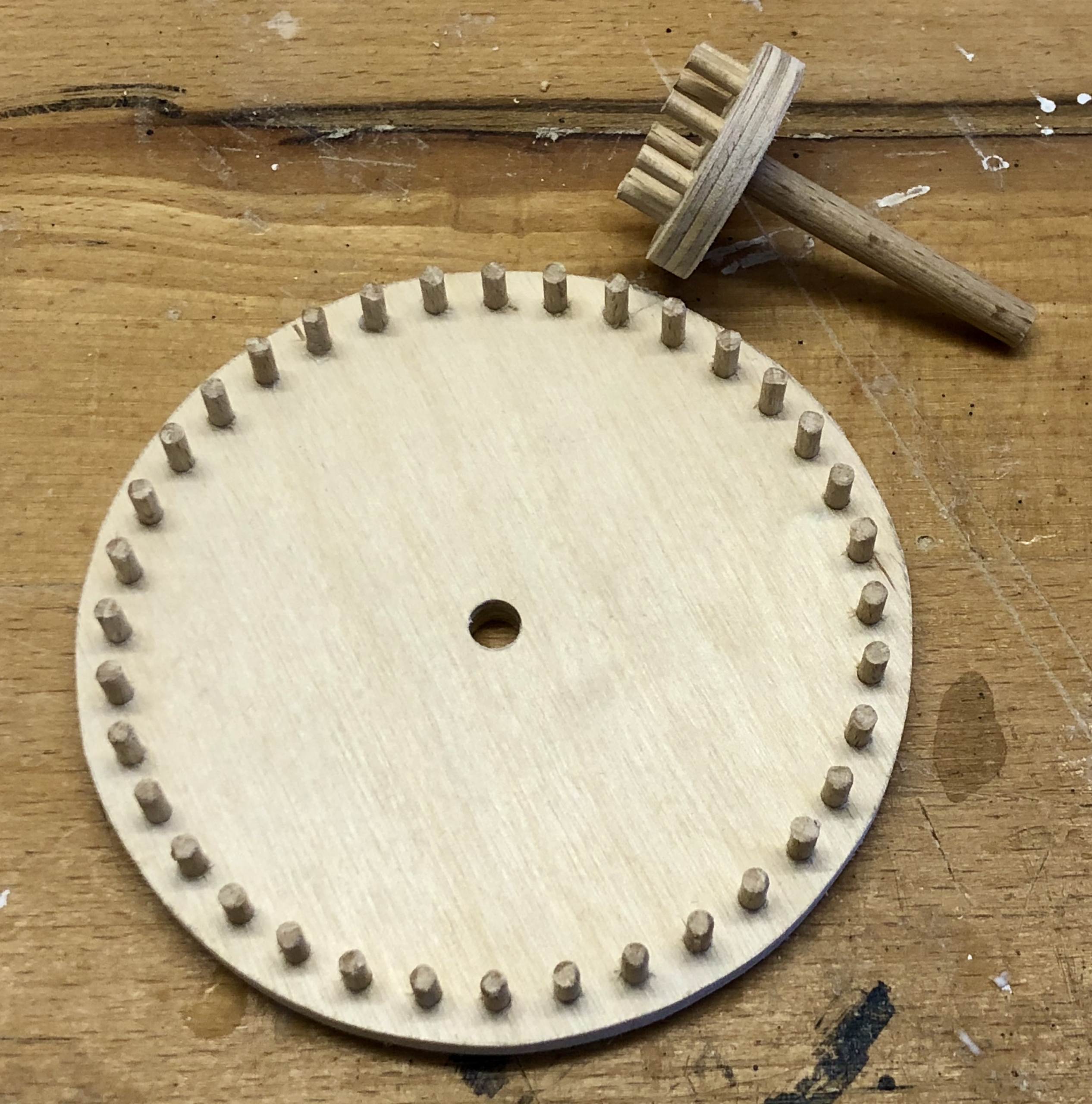
My original design for the base shows two identical cogs, each with 20 teeth. I used https://woodgears.ca/gear_cutting/template.html to produce and print their design, I glued them onto some 10 mm plywood and cut them out. But why, did I need cogs at all? As the slotted mechanism to move the boots, slides back and forth in front of the cam, it is not possible to simply extend the cam’s centre axle and fit a crank handle to its end. My solution to this problem is to use two cogs to effectively move the drive axis outside of the cam.
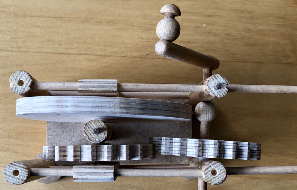
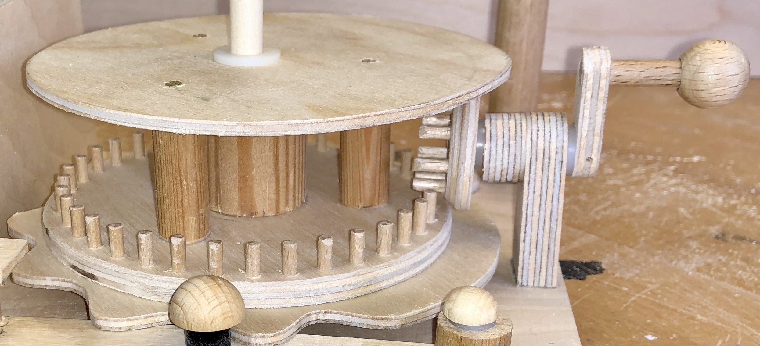
This is easier to understand from a picture taken from above the mechanism.
Here you can see 5 pillars made from 12 mm dowel. There is one pillar at each corner and one towards the centre. This centre pillar holds the short axle which joins the cam to the left-hand cog. As the crank is turned, it turns the right-hand cog which in turn drives the left-hand cog, making the cam rotate.
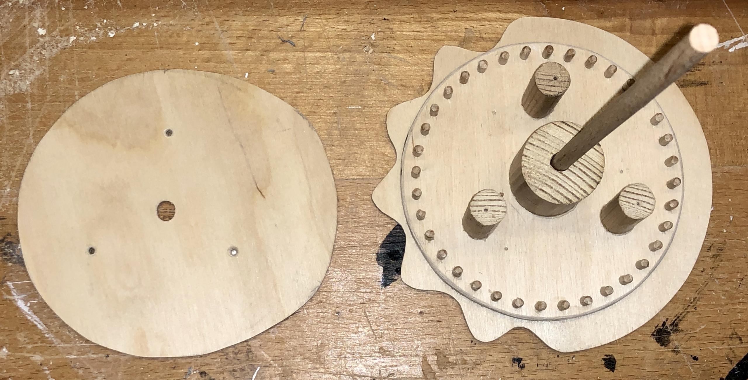
Just showing the cam and cog on an axle through the central pillar
The left-hand cog also has a pin in its outer face to drive the second slide
As the cog is turned, its pin then moves the slide backwards and forwards, thus moving the boot.
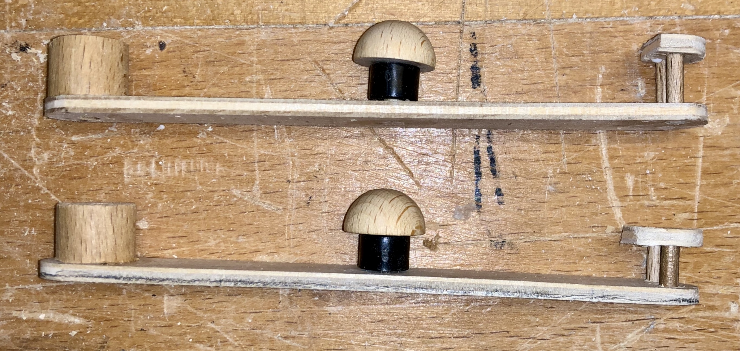
The hinge
So far there is no connection between the dog and the base so we need a hinge.
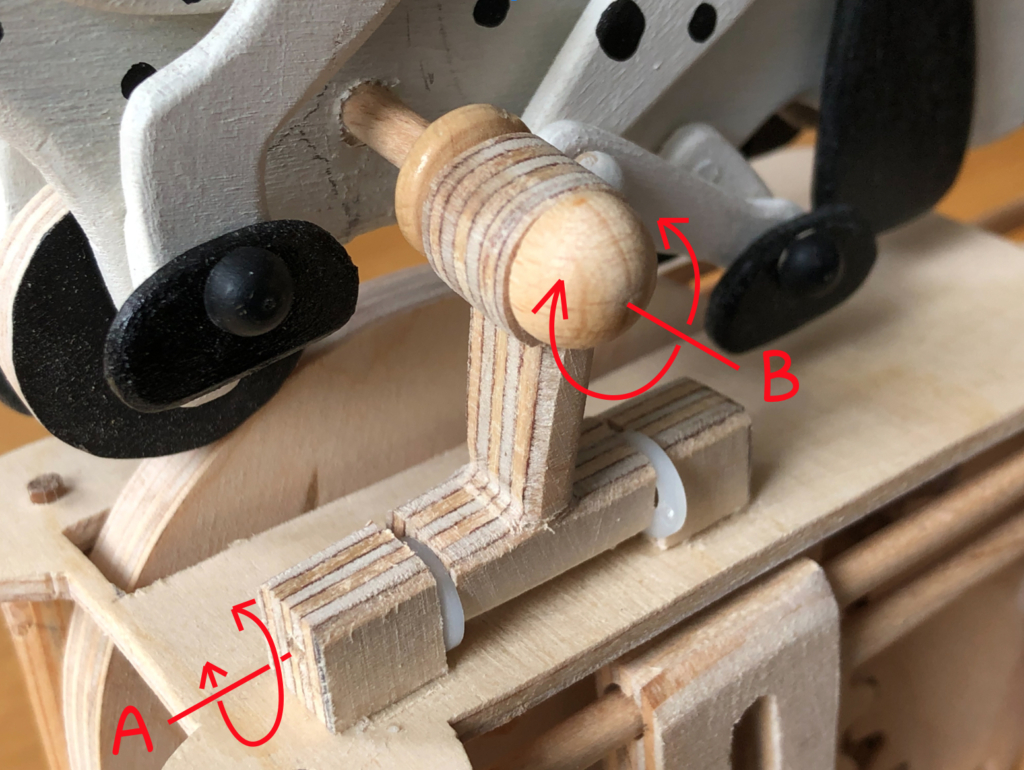
Hinge with two degrees of rotation
A piece of 4 mm dowel is fixed to part of the dog’s body where the moving legs can’t bump into it. This dowel can turn around axis B allowing the dog to tilt gently forward and back as the irregular cam turns. To make sure that both wheels stay in contact with the cam, rotation around axis A allows the dogs whole body to move gently up and down. This all means that the dog’s movement is more lively and interesting as it tracks the profile of the rotating cam. I chose not to restrict the rotation around axis A which means that the dog can swing wildly if you pick up the finished thing too impetuously. This may be a problem with children, but I’m sure adults will be more cautious. My dog did tend to loose contact with its rear wheel so I added a weight inside the body, above the rear wheel which fixed that problem nicely.
Left-handed
I didn’t intend to make it suitable for left-handed use, but that’s how it turned out. With the boots at the left-hand side you naturally want to hold the base with your right hand and then turn the crank with your left hand. I thought about putting the crank on the other side to make it right-handed, but then you would be looking at the side with the hinge and I preferred to avoid that.
Lucky lefties! But hey why ever not? When I build something for the first time I find that I can never think of everything in advance. My brain starts to hurt. After my day’s ration of decisions has been used up, I just wait with interest to see how things turn out.
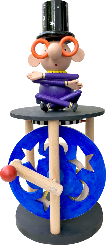
My yoga practitioner rather likes to wear a star-studded top hat while doing the daily exercises. As the hat kept falling off while doing the traditional cross-legged leaps, it seemed more useful to drop the hopping about and to concentrate solely on levitating the headgear. This requires years of practice and only the most experienced can master this extremely advanced technique. The very best practitioners eventually achieve a state of wisdom manifested by an owl appearing beneath their topper. A red owl shows a counter-clockwise attitude to life whereas a green owl definitely reveals a clockwise sense of being. Just turn the handle and be amazed at what you can discover about yourself.
The Technical Brief
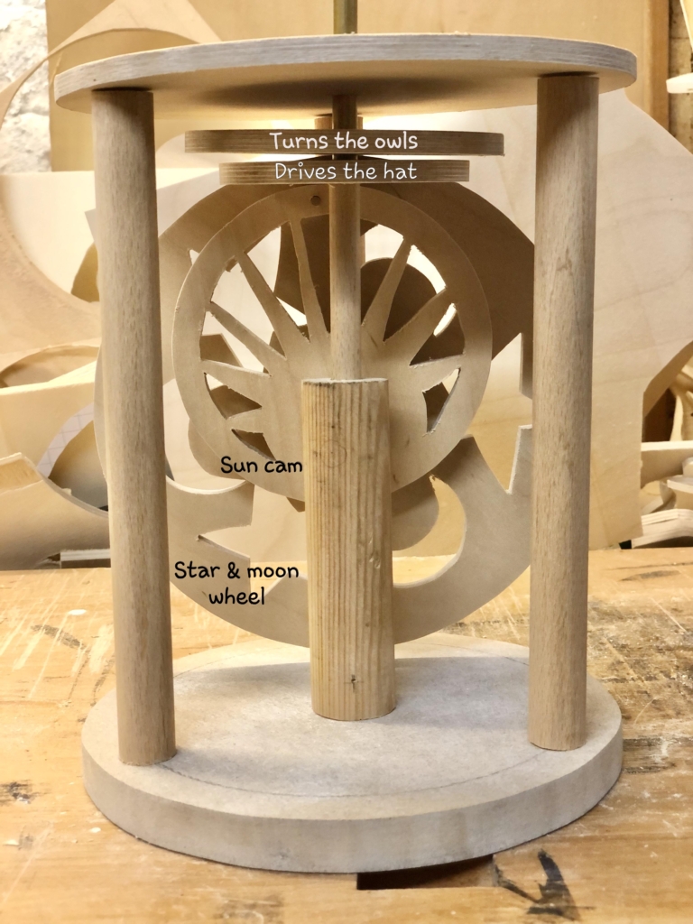
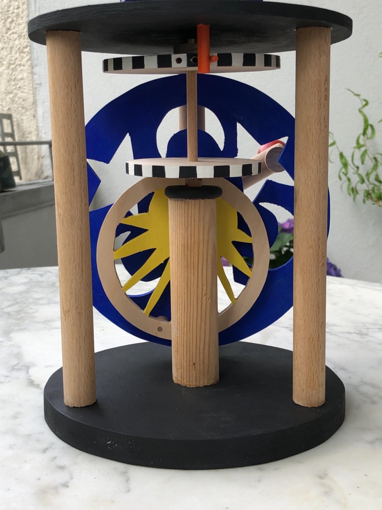
The mechanism is simply based on a very eccentric cam and a drive wheel on the same horizontal axis. These both friction-drive wheels attached to two coaxial vertical shafts, one hollow one not. The eccentric cam doesn’t just rotate its wheel, but lifts it up and down by 5 cm (the size of the owls). Its wheel is attached to the hat via a wooden dowel which turns loosely inside a brass tube. The other driven wheel is connected to the brass tube which passes freely through the figure and its other end is attached to the owls. This wheel must only turn through 180 degrees to show the correct coloured owl. As the biggest drive wheel is quite large, a largish base is needed to accommodate it. Making up more than one half of the whole assembly my feeling is that it then needs to be interesting in itself. To this end I chose a round base, a very open structure so that you can see everything that goes on, and I cut decorative holes in the drive wheel and cam.
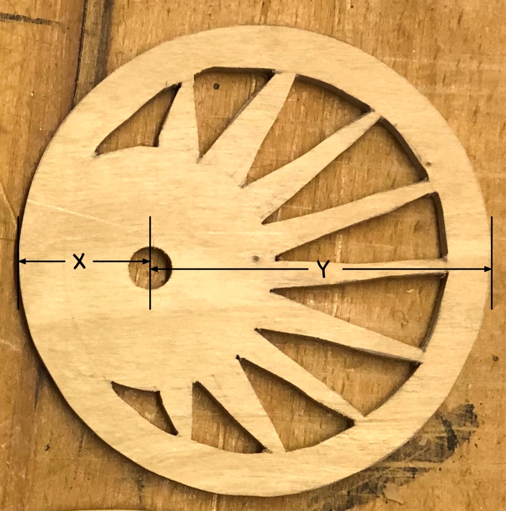
The Sun Cam
The “sun” cam is mounted on the axis which is turned by the crank. It has to provide an up and down movement of 5 cm. I chose X to be 3 cm and Y to be 8 cm which gives the required difference of 5 cm. To add to the slightly mystic flavour of the piece I cut a sun pattern. The sun does go up and down after all and with a bit of yellow paint it does look quite sunny. Note that I didn’t paint the outside circumference of the cam as it rubs against the wheel which it drives and the abrasion would quickly wear the colour away.
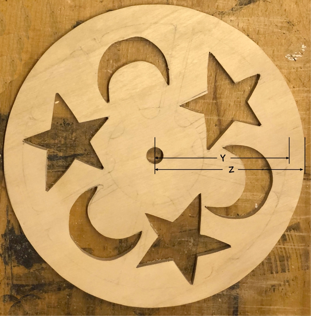
The Star and Moon Wheel
The “star and moon” wheel to turn the owls around has to have a larger radius Z=9 than the cam’s largest radius Y=8. This is to allow space for the wheels which are friction-driven. As this is a nighttime pattern, I painted it dark blue which is a nice contrast to the “sun” cam.
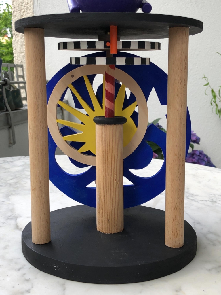
The Wheel which turns the Owls
This wheel is glued to a brass tube. The other end of the tube is attached to the owls. To prevent this wheel from being turned by more than 180 degrees, I have inserted two pieces of 3 mm dowel which bump up against a piece of dowel which protrudes down beneath the top of the base.
The 180 degree stop
Once the stop is reached, although the “sun” cam continues to turn, it now just slips on the wheel, until the crank is turned in the other direction which will then result in a reverse 180 degree turn.
The Wise Owls
This strange looking beast is a 5 cm tall owl, or rather 2 owls back-to-back. This is why it has 4 eyes and two beaks. The hole drilled vertically through it is a snug fit on the brass tube. Turning the crank clockwise turns the green owl to the front. Turning it counter-clockwise rotates it by 180 degrees to bring the red owl to the fore.
Front view of the owls
The Figure
The figure has no moving parts, it is just a support for the owls and its hat with a vertical hole all of the way through which allows the brass tube to turn freely. I went for simple crossed arms and legs, which is my version of the correct pose for yogic flying. The figure is as short-sighted as I am, so of course it needs a pair of spectacles. The top ring serves as a nest for the owls.
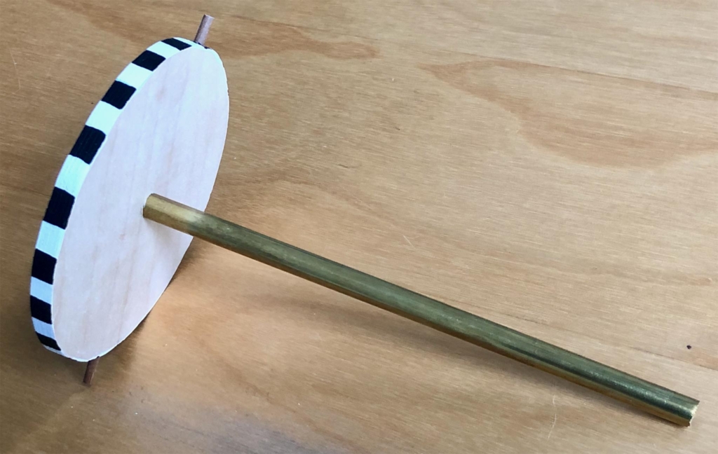
The Hat
I needed thin walls for the hat, so that the owls have space to do their turns. An old plastic tube was just the right size, if a bit of a nuisance to paint, but I managed to find some suitable black gloss paint for a starry night. This also turned out to be so lightweight, that it would go nicely up but would then hesitate about coming down. A lead weight right at the top fixed that while leaving space for the owls.
The Drive Shaft for the Hat
The thin part of the shaft runs inside the brass tube and is attached to the top of the hat after passing through the owls. The thicker part rests loosely in a hole drilled in some 25 mm dowel which is fixed to the bottom part of the base. It was OK to paint the outer circumference of the driven discs as they don’t touch anything. Using a strong pattern makes the movement very clear.
Hat downHat levitated
Reflections
The base is quite large owing to the need for a simple cam to produce 5 cm of vertical movement. I toyed with the idea of using a lever to multiply the cam’s movement, but without the rotation it would then not have been possible to magically change between red and green owls. There is probably a more complex solution which would do what is required in less space, but everyone wants to see how the mechanism works anyway, so having everything out in the open and brightly coloured makes it all a part of the show.
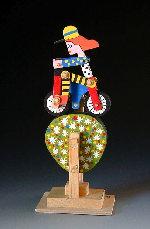
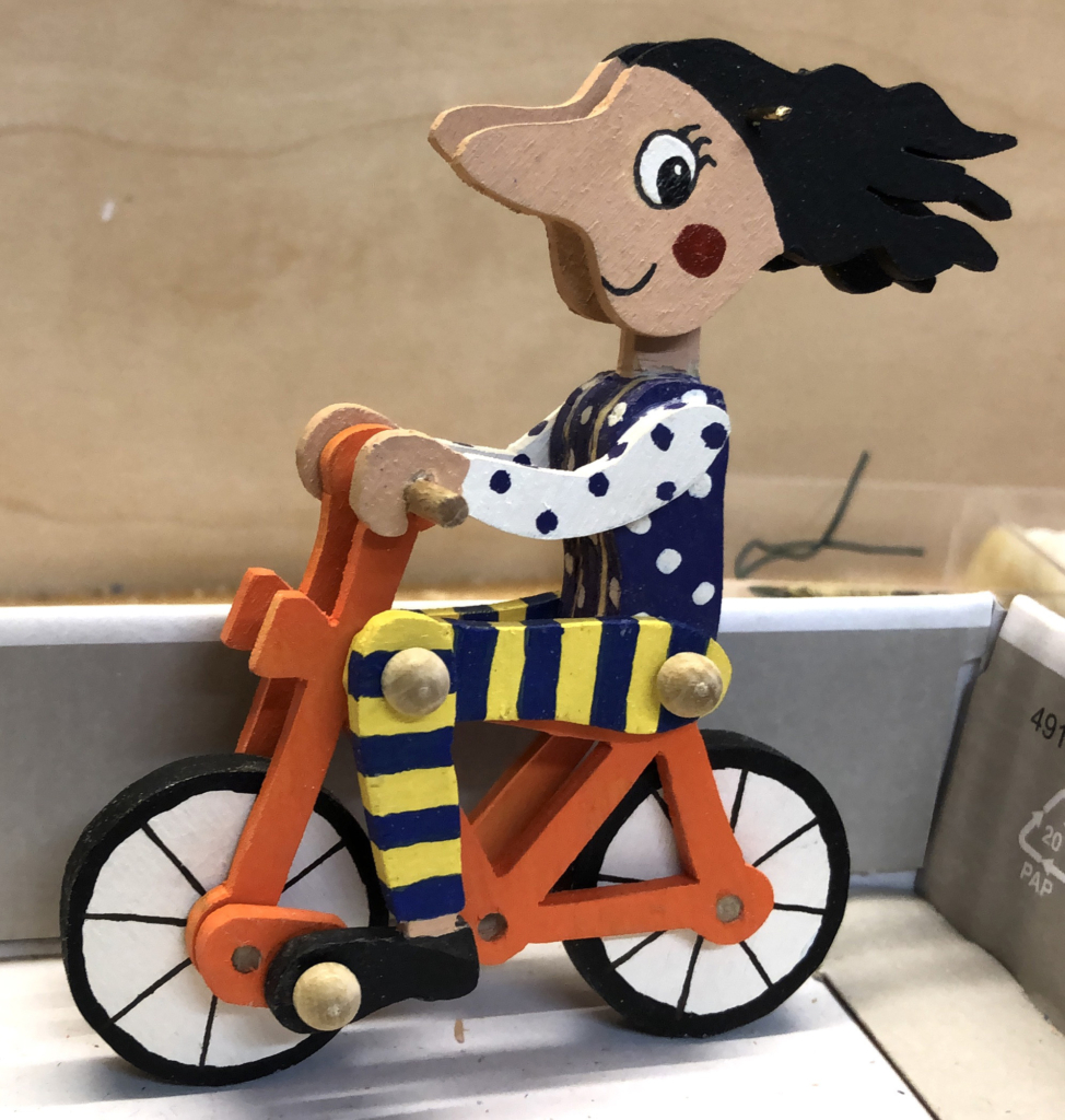
The other day I came across a video of Peter Markey’s wonderful “Cyclist” (see http://www.contemporaryautomata.com/videos/cyclist/index.html) and I liked the movement. Not only does the small figure pedal madly like a child on a tricycle, but the road goes up and down, making the bicycle tilt forwards and backwards. “I’ll have a go at that,” I thought and mentally added a small change to the figure’s head to allow it to also swing about, adding quite a bit more movement.
Design
Instead of setting off straight into the workshop, I thought for a change that I would try drawing my design in some detail and in doing so make it easy to print out templates which I could trace around on sheets of plywood ready for cutting.
I used a drawing application called Graphic for Mac. This has layers, so that I could draw each part on a separate layer, rather like layers of plywood. It’s not expensive 3D software, so I couldn’t do a full design at my desk, but I could check out basic things such as checking that the knees do not bump into the handlebars while pedalling.
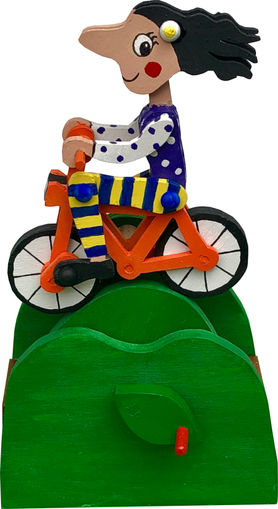
The layered design of A Happy Cyclist
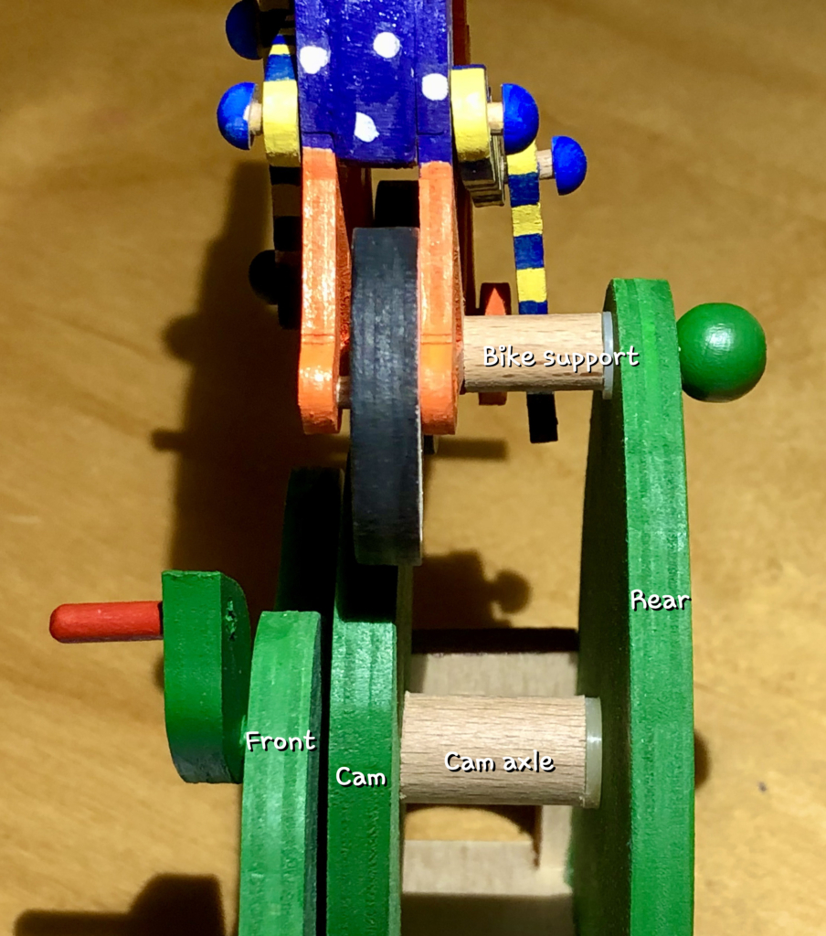
I chose to use a landscape with 3 green hills. The front and back hills are fixed and provide a framework to hold the axle for the crank as well as a tilting support for the bicycle. The middle hill isn’t really a hill at all but a rotating cam with ups and downs to make the ride more interesting. A rolling landscape.
Cause and action are reversed here. Turning the crank moves the road, which turns the wheels, which make the feet move. The viewer however gets the impression that the figure’s legs are pumping making the wheels turn etc.
Cutting spokes is an unnecessary complication. I thought it would be quite OK to leave the wheels solid and just paint the spokes, following Peter Markey’s example.
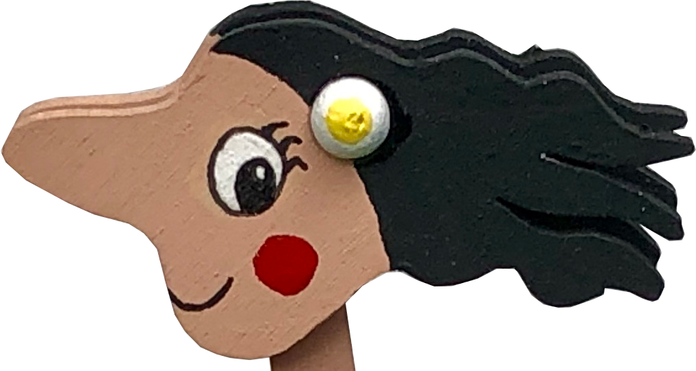
To make the head swing free, it is made up of two parts which are joined at the top by a piece of brass rod. Trial and error tells you where to drill the pivot holes and small wooden hemispheres on each side serve both as a flower in the girl’s hair as well as increasing the surface area to which the brass rod is glued thus making a stronger joint.
Head with a minimalist flower covering the end of the brass rod
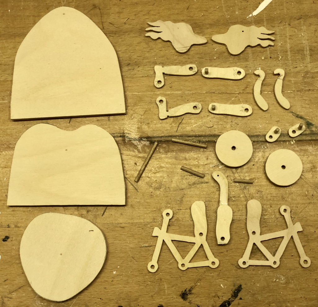
Making
Parts cut out using card templates
Having drawn all of the shapes with a computer it was easy to to print out the individual shapes on some card, which I then cut out with scissors to make a set of templates. My bowsaw made short work of cutting out the bike from 3 mm plywood and the wheels and hills from 6 mm plywood. The centre part of the body determines the spacing between the two halves of the bicycle frame, so it has to be a little thicker than the wheels to allow them to rotate freely. The joints are made with 3 mm dowel.
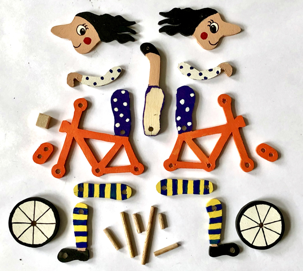
Painted parts
It was only sensible to paint the parts as far as possible before assembling the figure and her bike.
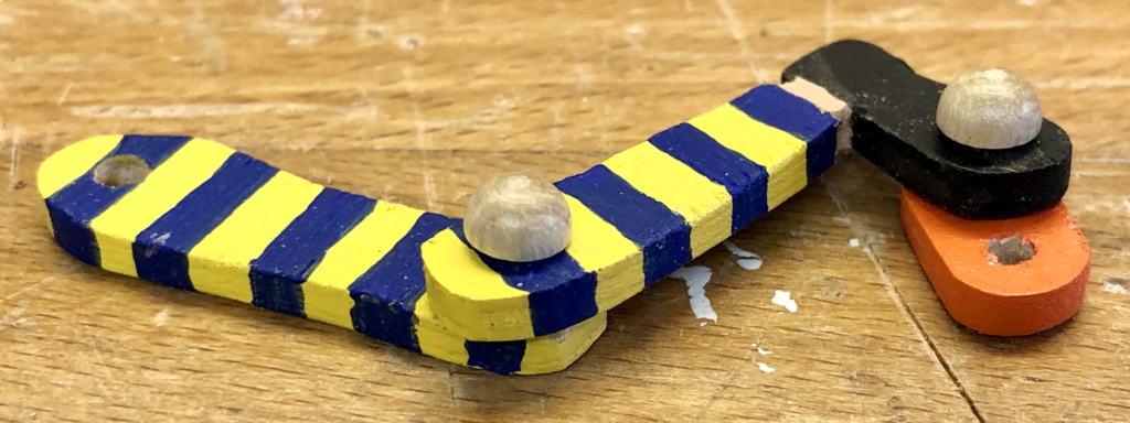
The left leg and “pedal”
The joints in the legs use 3 mm dowel. To ensure free movement, the hole in the moving part is 3.5 mm and a small wooden hemisphere on the end of the dowel prevents everything from falling to pieces when the pace picks up.
The partially assembled cyclist
Once I had provisionally assembled the cyclist and had checked that she pedals nicely when rolled along the workbench it was time to consider how to attach the bike to the landscape.
Side view
As the shape of the cam on which the wheels run is not a regular circle, the bike has to be able to tilt forwards and back when cycling downhill and uphill to maintain contact with the road. A piece of dowel glued to the base of the bike can rotate in a hole drilled in the rear hill. A certain amount of up and down movement is also needed to keep the wheels on the road. I had thought of making a fairly complex pivot to allow this, but it turned out to be unnecessary. The play between the dowel and the hole in the rear hill was enough to keep everything moving.
Final Touches
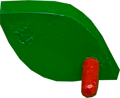
Turn over a new leaf
The lever that you use to wind an automata into movement is often boring, so on a whim I went for a leaf shape, as everything was so pleasantly green. You can play with the words here as in “Turn over a new leaf and go for a ride on your bike”. It amuses me, even if most of my German friends look completely blank. I usually make the part that you grab hold of red as a signal – “start here”.
Also something is required to keep the front and rear hills parallel to one another and I started with a boring rectangle. Imagining myself cycling through the hills of sunny Italy I thought let’s have a tunnel instead. Italians are master tunnel builders, which is handy given how many hills they’ve got.
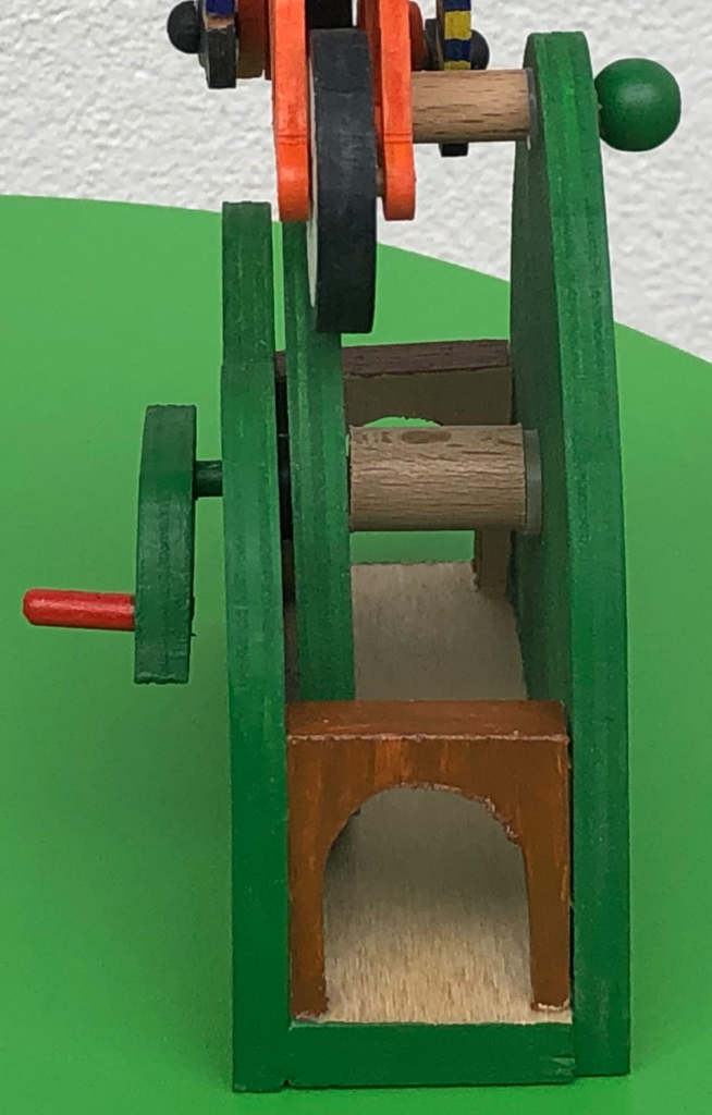
Have you ever thought how you can make hair move? Inspired, as so often, by an image from the Internet, I wondered first of all how to make triangles hanging from the circumference of a head stand up. It seemed pretty complex to me and I wasn’t sure that the result would be worth the effort. Then I noticed that I still had a few bases for thumb push puppets lying around so I decided to stretch the concept a little of what hair looks like.
The Requirements
This is fundamentally a fairly simple project and the idea is that when you pick the figure up and press its base the hair should move. A standard thumb push puppet has one spring in the base and four strings attached to a disc on the bottom of the spring. Having only four strands of hair seemed a bit thin to me so I went for eight instead.
There is however a reason why four is the standard number and I guess that it has to do with keeping the tension about the same for all of the strings, when no one is pushing the base up. The spring permits the disc in the base to tilt in any direction, thus compensating for some of the differences in tension at four points on the circumference. Having eight points around the circumference might bring the points too close together for tilting to effectively correct for differences in tension. My quick fix for this is only use four points but, instead of fixing each string to the point, I arranged for a smooth anchor bar around which each string can slide thus allowing both ends of each piece of string to be used up on the figure’s head. If the friction is low, the tension at the two ends will be very similar. This results in eight ends to play with and the tilting of the disc can compensate for slight differences in tension as usual.
Making
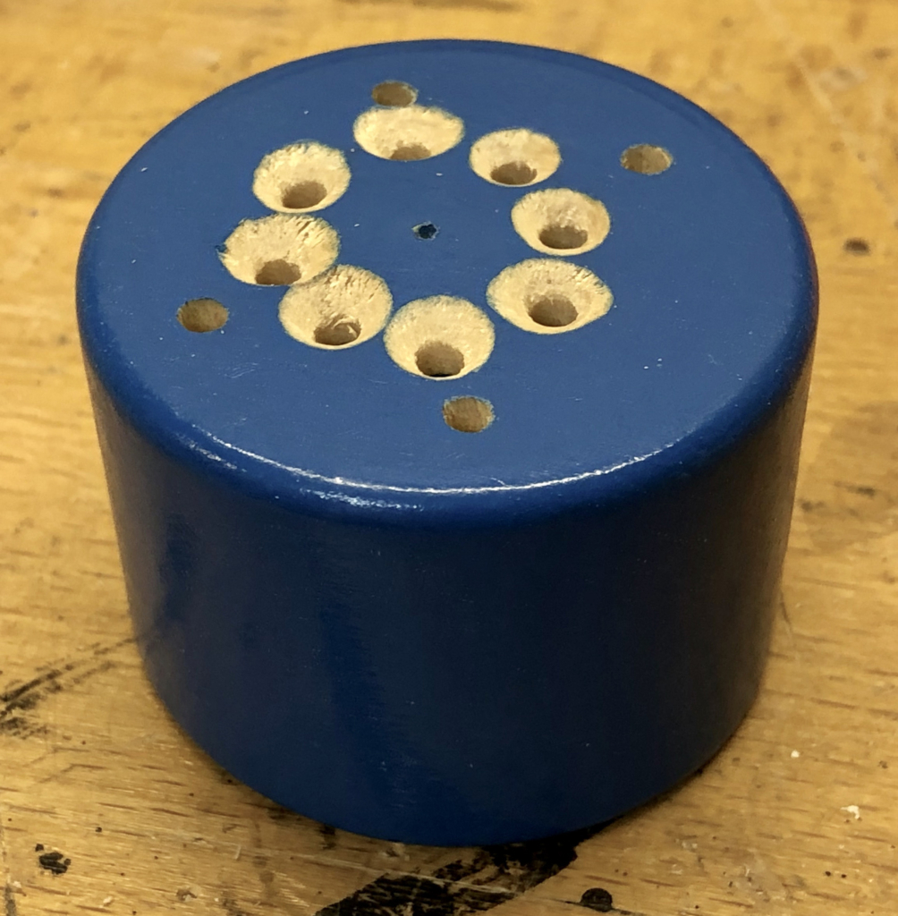
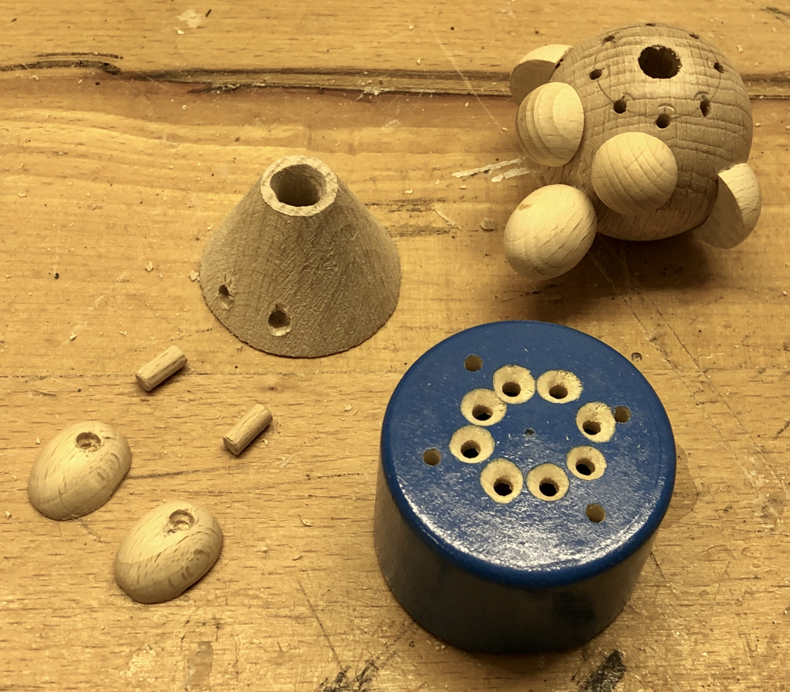
Recycled base with 8 new holes and 4 old, unused ones
The base needs eight holes for the four pieces of string. The figure’s dress will cover the four old, unused holes.
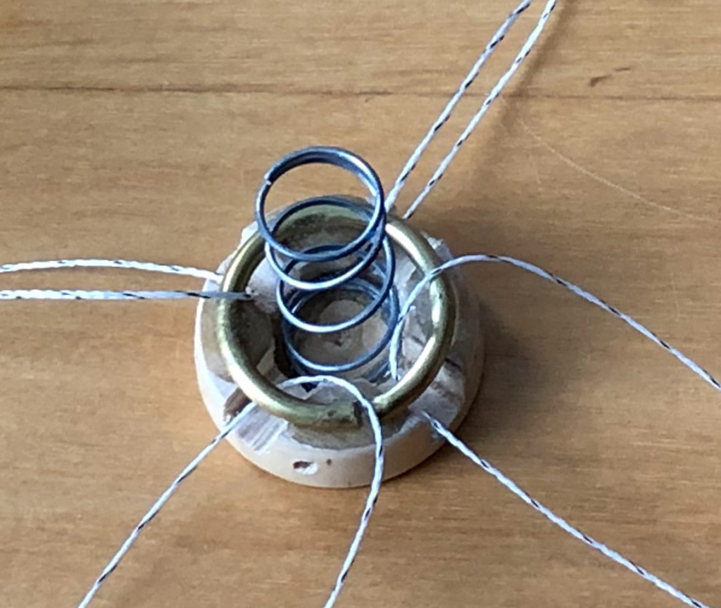
Disc with spring, brass ring and four strings
I modified the original disc which fits into the base by cutting four notches and gluing a piece of bent brass rod on top with epoxy resin adhesive. This arrangement leaves plenty of space for each string to slide easily.
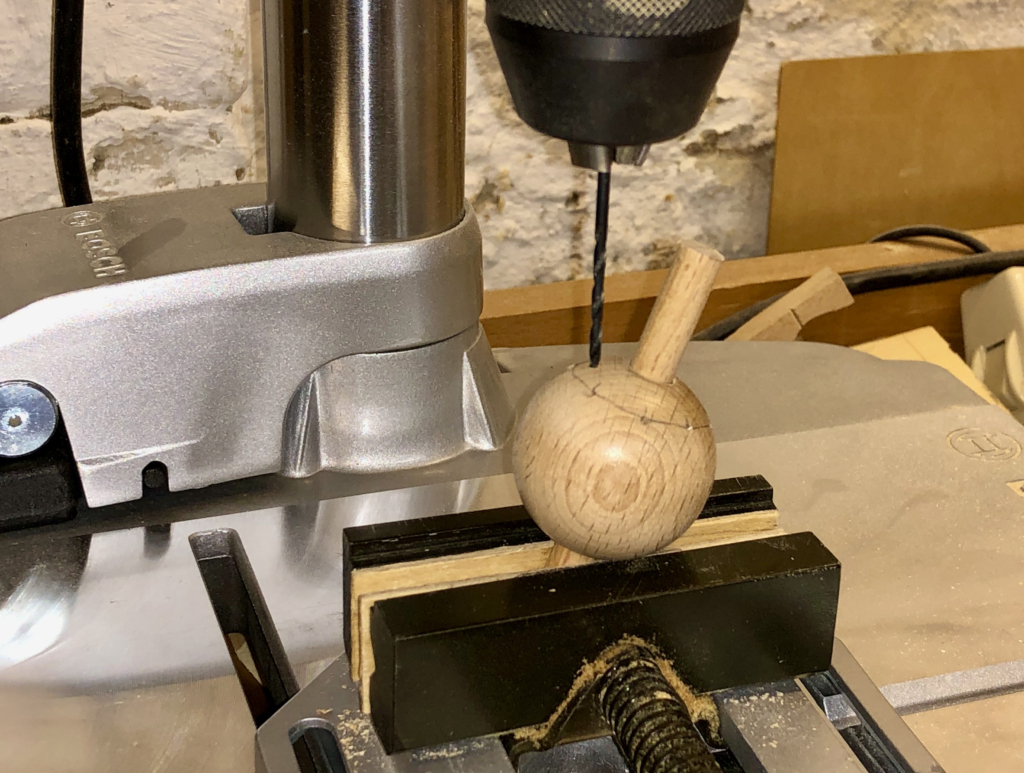
Drilling slanted holes in the head
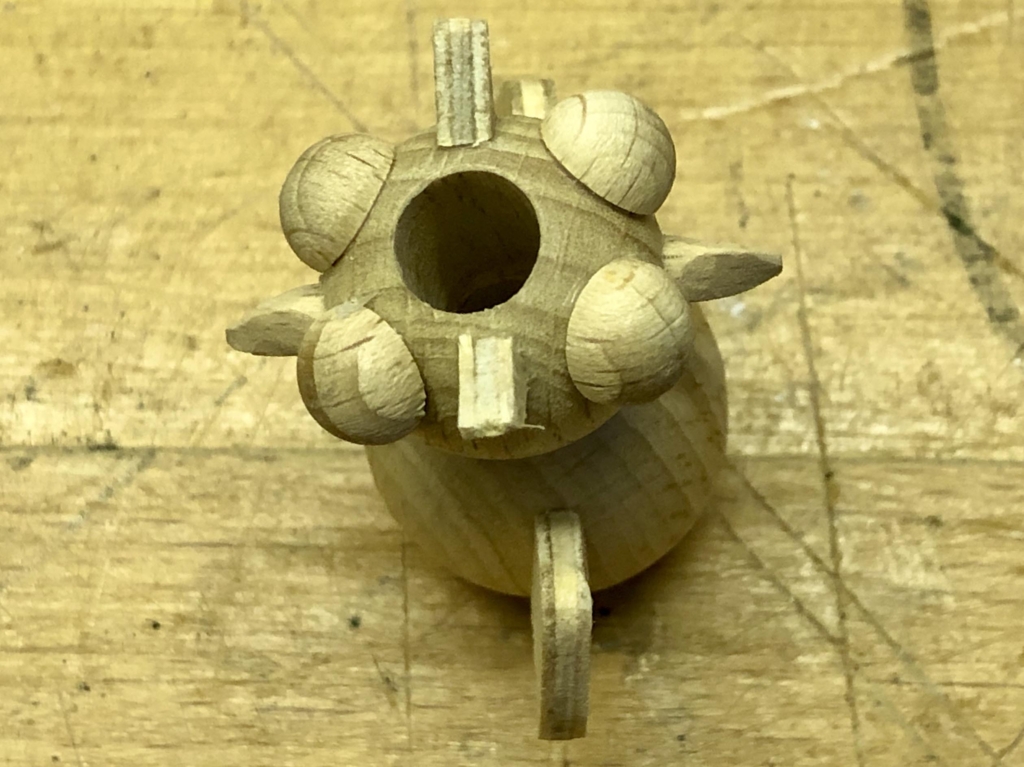
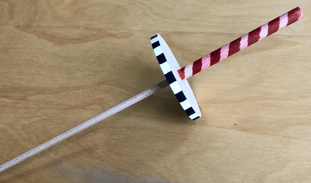
The head is a 40 mm diameter beechwood ball predrilled with an 8 mm through hole. Slid onto a slanted piece of 8 mm dowel this can be rotated to drill eight holes which are suitably spaced for hair at the top, but which are slanted so as to come together at the neck hole.
Body parts and base
The figure’s body is a beechwood cone with the tip cut off and a through hole, widened at the bottom with carving tools. The strings come out of the holes in the base, pass through the conical body, out of the neck hole and into the head, where each string has its own hole from the neck up onto the top of the head.
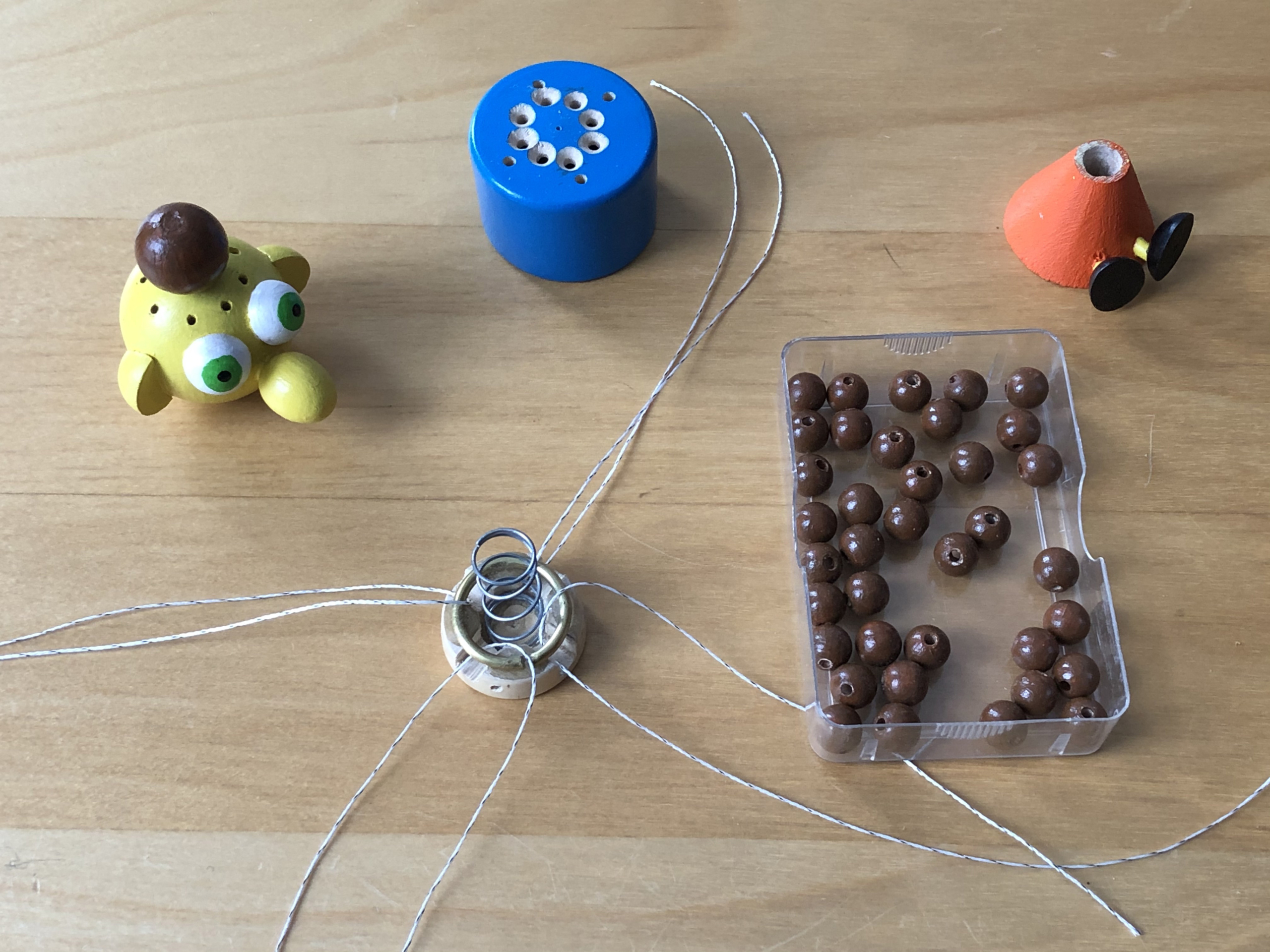
Painted parts ready for assembly
Before the final assembly, the parts have to be painted.
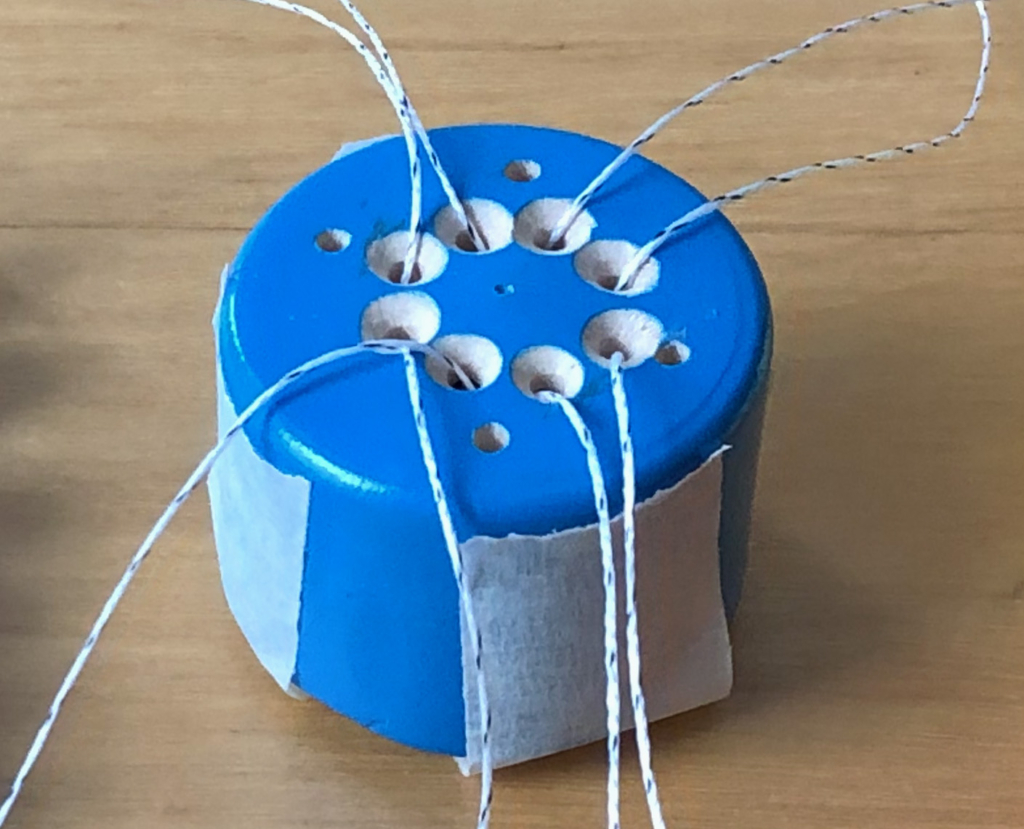
Compressing the spring for assembly
I used masking tape and a block of round wood to press and hold the disc up, compressing the spring a little and holding it in place while the strings are threaded up through the figure.
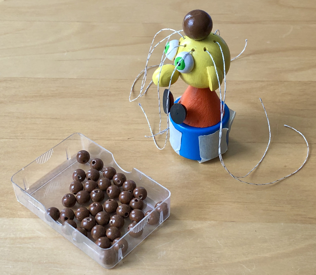
Strings threaded through the body and head
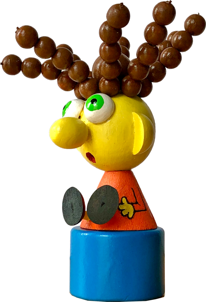
I used kite-flying string as it is both flexible and strong. Patience is required while threading, but using long strings helps. Five small brown balls go on each string and the last one to go on is then glued in place after closing the hole with a tiny piece of dowel which also jams the string as it is pushed in. It’s important to tension of all eight strands of “hair” about the same, so that they all stand up when the spring is released. If one string is less tense than the others, two strands of hair will flop down and spoil the effect. It took me three goes and much gnashing of teeth to get this right.
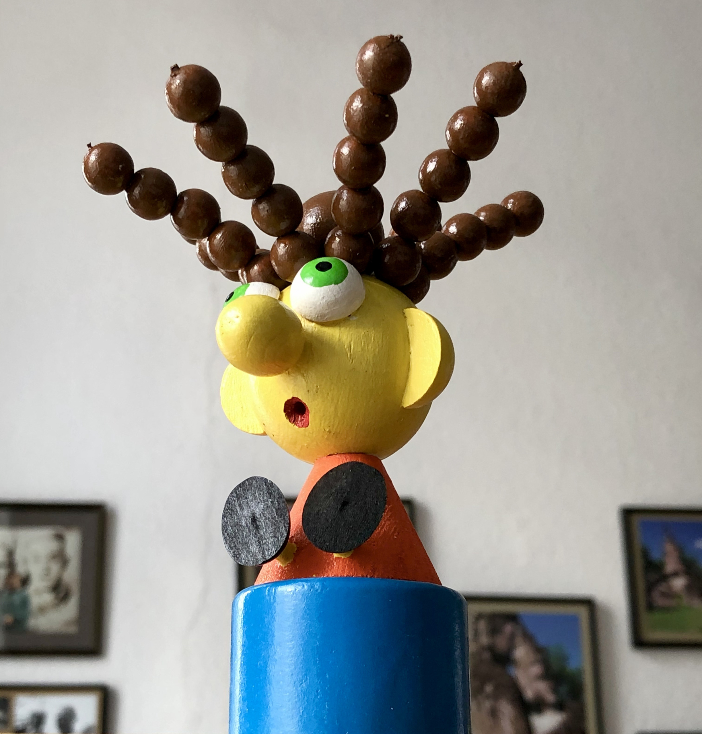
Hair finished and equally tensioned
I almost added arms to the conical body but decided they would just make it harder to hold and operate, so I painted them instead.
For the video I borrowed the story from a well-known English nursery rhyme. https://www.youtube.com/watch?v=fB6XfBY2um8
Little Miss Muffet Sat on a tuffet, Eating her curds and whey; There came a big spider, Who sat down beside her And frightened Miss Muffet away.
I have no idea what a tuffet is. In my case it’s obviously blue, whatever it is. In retrospect my thumb puppet could have been a cranked automaton where a spider appearing causes her hair to stand on end. Some other day perhaps.
Some while ago I enjoyed a video produced by an Italian artist Giuseppe Ragazzini (https://www.youtube.com/watch?v=VurUCgxdp8E) and I thought it would be fun to make my own real world, wooden version which doesn’t need an internet connection. Then a friend gave me some doll’s eyes, the sort of eyes which close when a doll is put to sleep. That was enough to finally get me started on the Bizarre Belle of the Ball.
Requirements
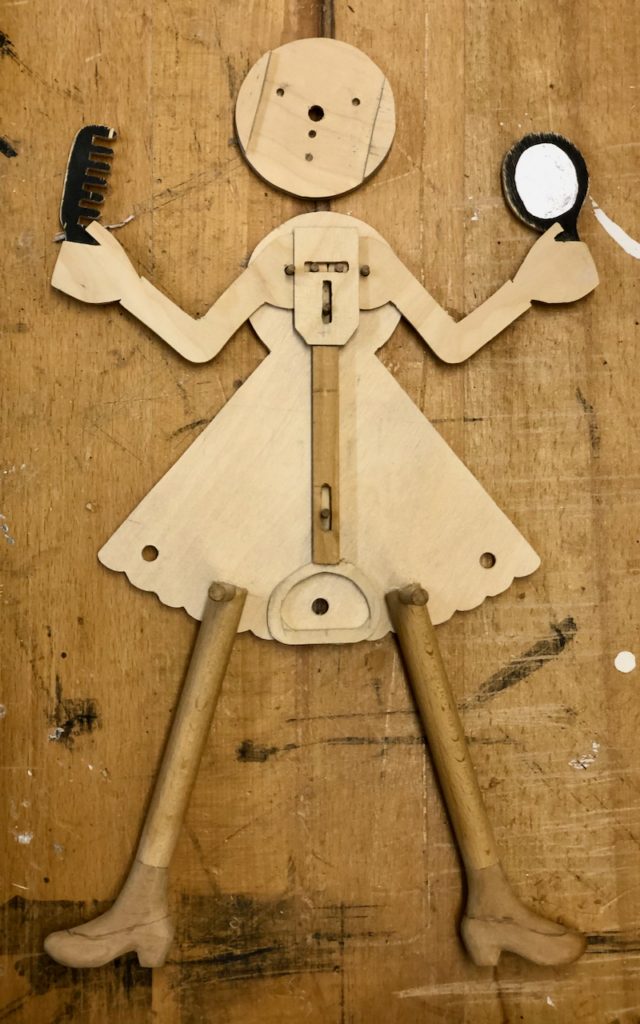
I chose to have 8 sets of eyes mounted on one disc, 8 noses on a second disc and 8 mouths on a third disc which is enough for 512 distinct faces so that our belle can go to 512 balls and never have to look the same twice.
To frame each face and concentrate the viewer’s attention on it, it seemed best to use our bizarre belle’s arms. Whenever her eyes are correctly aligned, both arms should come up. To make it a more convincing gesture, she should hold a mirror in one hand to admire the finished effect and a comb in the other to tidy her non existent hair. One turn of each control knob should rotate the disc through exactly one eighth of a turn.
Making
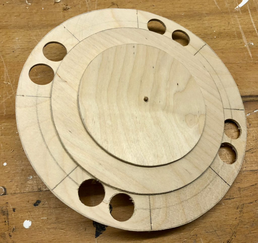
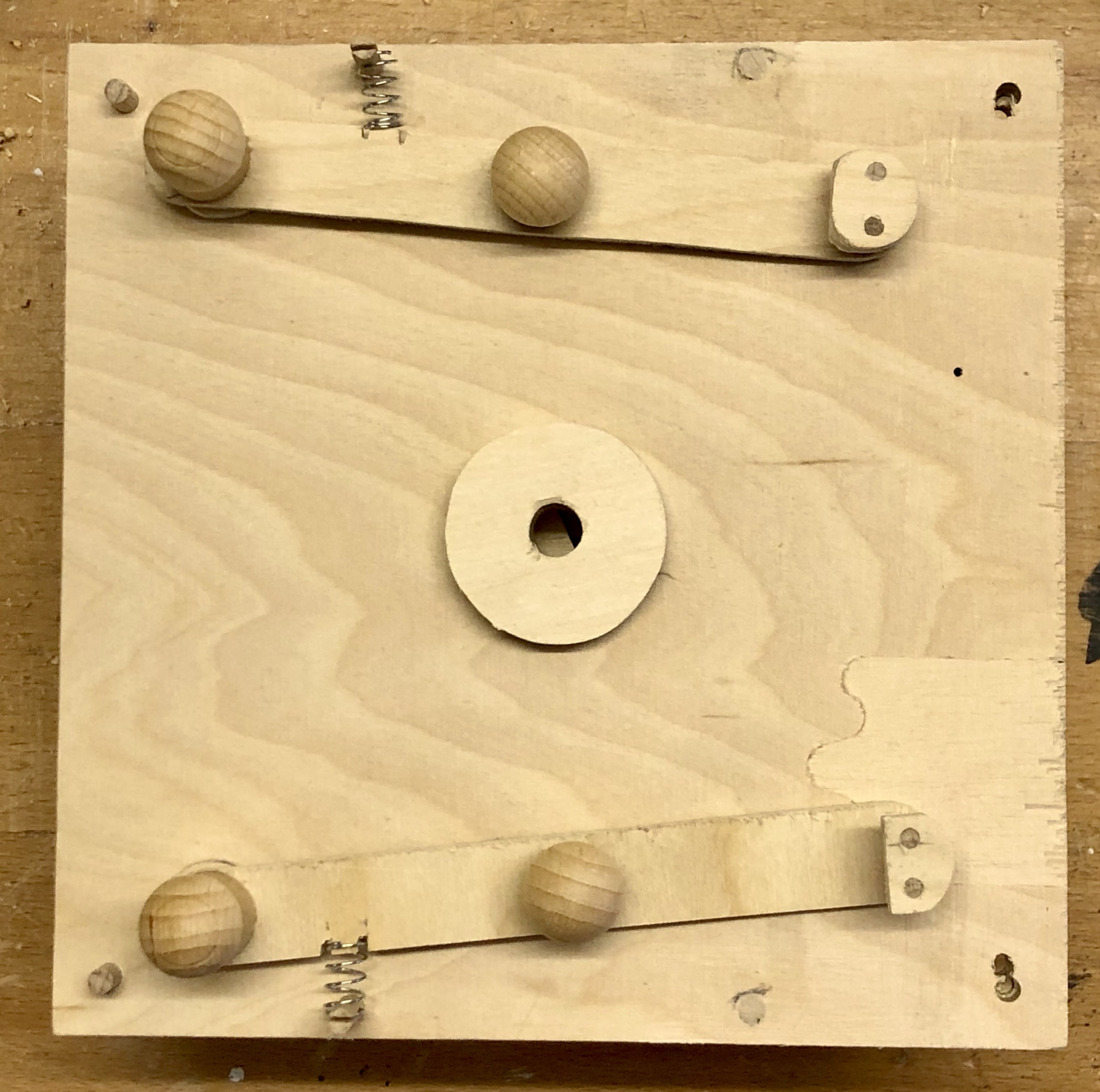
The smallest 3 mm plywood disc is attached to a solid 6 mm axle. This axle runs inside a thicker hollow axle for the middle-sized disc. The largest diameter disc turns around both with several spacers joining the disc to its cog while leaving room for the doll’s eyes.
three discs to mount the eyes, noses and mouths
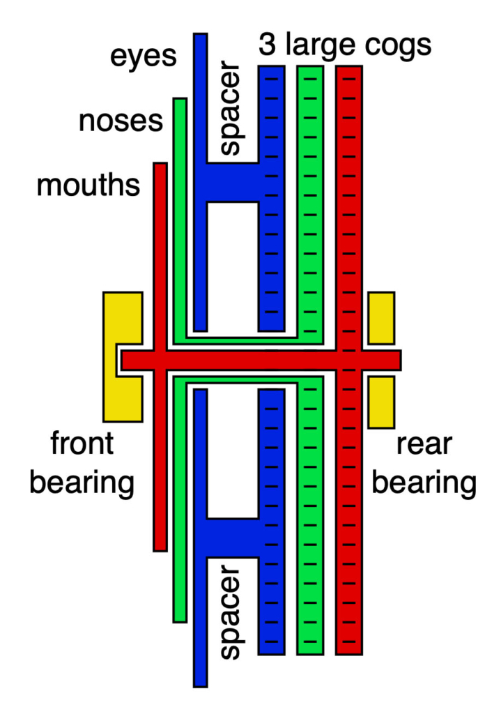
If that sounds complicated, here is a section through the middle. This means you are looking at these discs from the side
section through the middle (not to scale)The “eyes” disc connected via spacers to its large cog
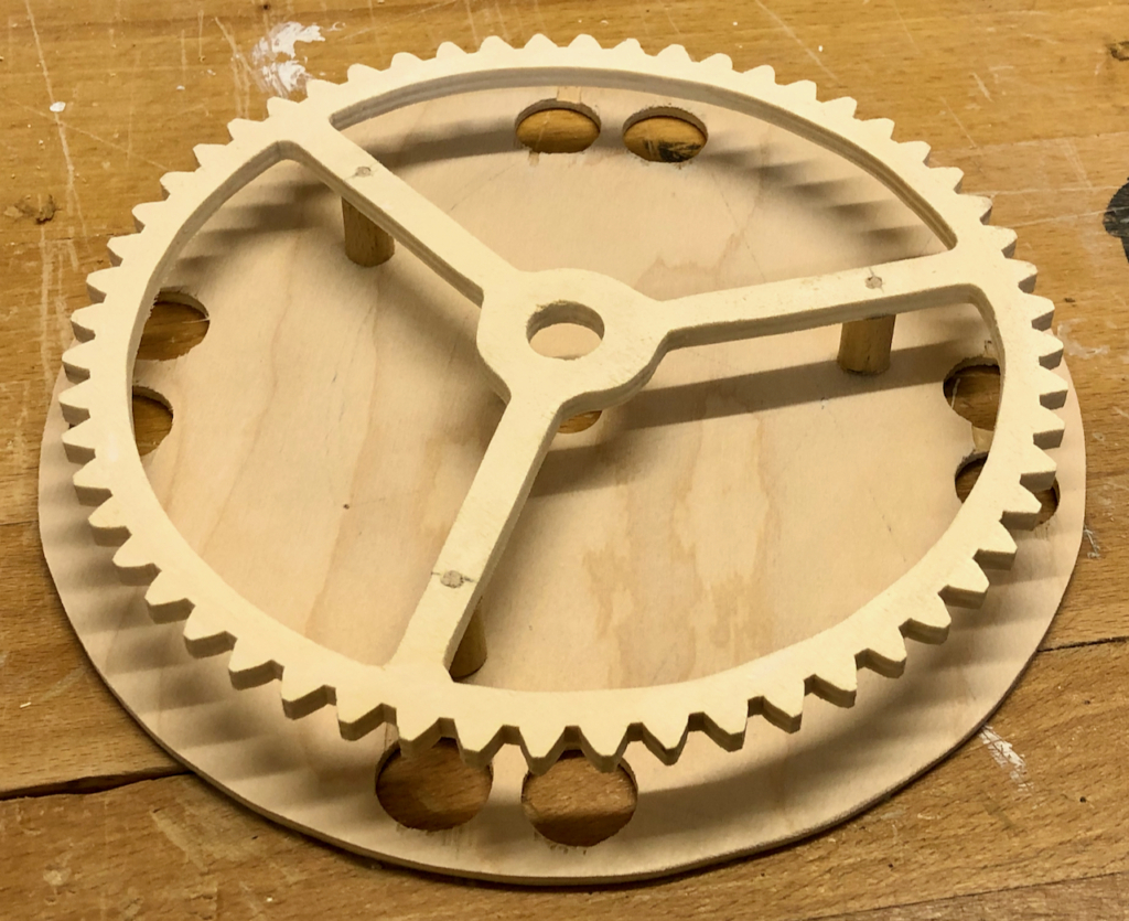
To make the 3 discs turn, you then need 3 large cogs behind them.
Three large cogs
Small cogs will drive the big ones, so the number of teeth is important to set the speed of rotation of each disc. With 8 noses etc., the number of teeth on the big cogs must be 8 times the number of teeth on the small cogs, so that one turn of the control by the user moves from one nose to the next. I chose 7 teeth for the small cogs which then means 56 teeth for the big cogs. I find that cogs with small numbers of teeth can jam easily and 7 is actually quite close to the limit.
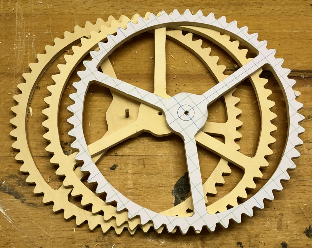
To shape the cogs I used Matthias’ splendid online gear template generator https://woodgears.ca/gear_cutting/template.html. To save time and work here, I first pinned three sheets of 6 mm plywood together, glued the template on top and then cut the three large cogs at once with my scroll saw.
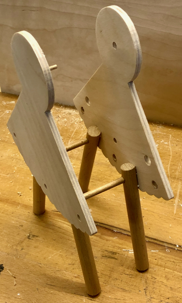
Body and legs
body front (left) and back (right) and four legs
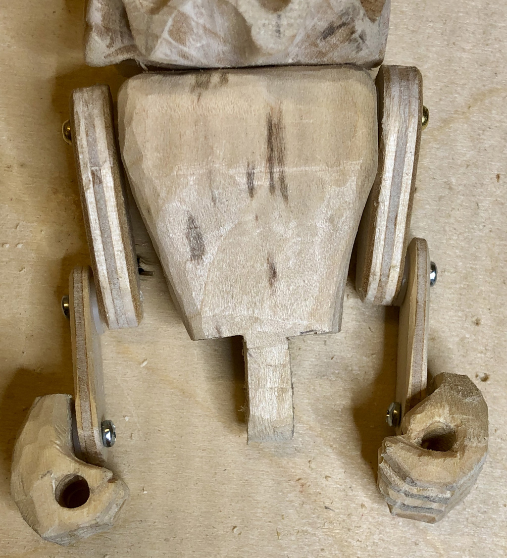
To hold the rotating discs and cogs some sort of frame is required. A dress with a wavy frill at the bottom and a round upper body seemed about right. Two legs would be a bit unstable, so my bizarre belle has four legs. The front part also has to take the mechanism to lift the arms up. Some elegant carved shoes are, of course, needed to equip our belle for the ball.
The front part of the body with the lifting mechanism for the arms
The hole between the legs takes an axle fitted with an eccentric cam. As the axle is turned the cam presses the vertical actuator down, which pulls the arms up. The loose round part at the top is the lid to keep all of the parts in place and it also has a hole in the middle which serves as the bearing for the axle for the rotating assembly.
The rear part of the body with 6 small cogs to drive the large cogs
The rear part of the body carries 6 small cogs, 2 for each large cog. They are each set at the correct height to drive their own large cog and hence the corresponding disc with noses (left) eyes (centre) and mouths (right). Each knob on the front of the figure turns an axle which turns one of the small cogs. The reason for the second, identical cog is to provide enough space for the hats on the largest dic to move unimpeded. As the two cogs are identical there is no change to the transmission ratio and one turn of the knob will still move its disc through one eighth of a turn.
Unpainted partial assembly
Putting the parts together after carving eight noses, our bizarre belle starts to take shape. I was surprised to see that, when near horizontal, the doll’s eyes close and open one at a time, as if they are winking at me. Only having four sets of doll’s eyes, I improvised eyes for the other four faces.
Lessons learned
I had originally planned to use three cranks in front of the dress to turn the parts, which would have meant putting the figure on a heavy base. I find that on the up-stroke when turning a crank, models tend to skitter around unless they are heavy enough or have a non-slip coating underneath. By changing to spherical knobs, which you have to twist to operate, the upward force disappears and with it the need for a base. Magic!
The video
It is easiest to understand the mechanisms when you can see them in action so here is our belle of the ball deciding how to look for her next ball. https://www.youtube.com/watch?v=gMLE70_scGE
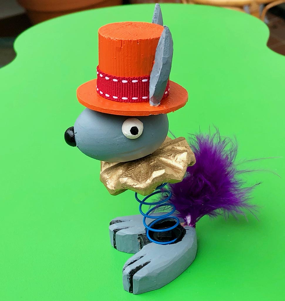
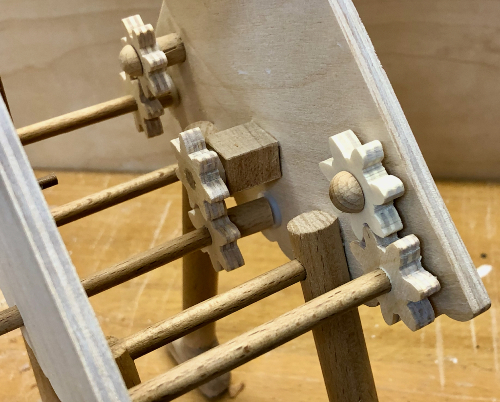
Recently I was playing around with an augmented reality robot on my mobile phone https://developer.apple.com/augmented-reality/quick-look/ (it doesn’t do much on a desktop computer). After a while of course you get fed up with virtual stuff and I thought that it would be more fun to make a tangible desktop robot with parts that really move.
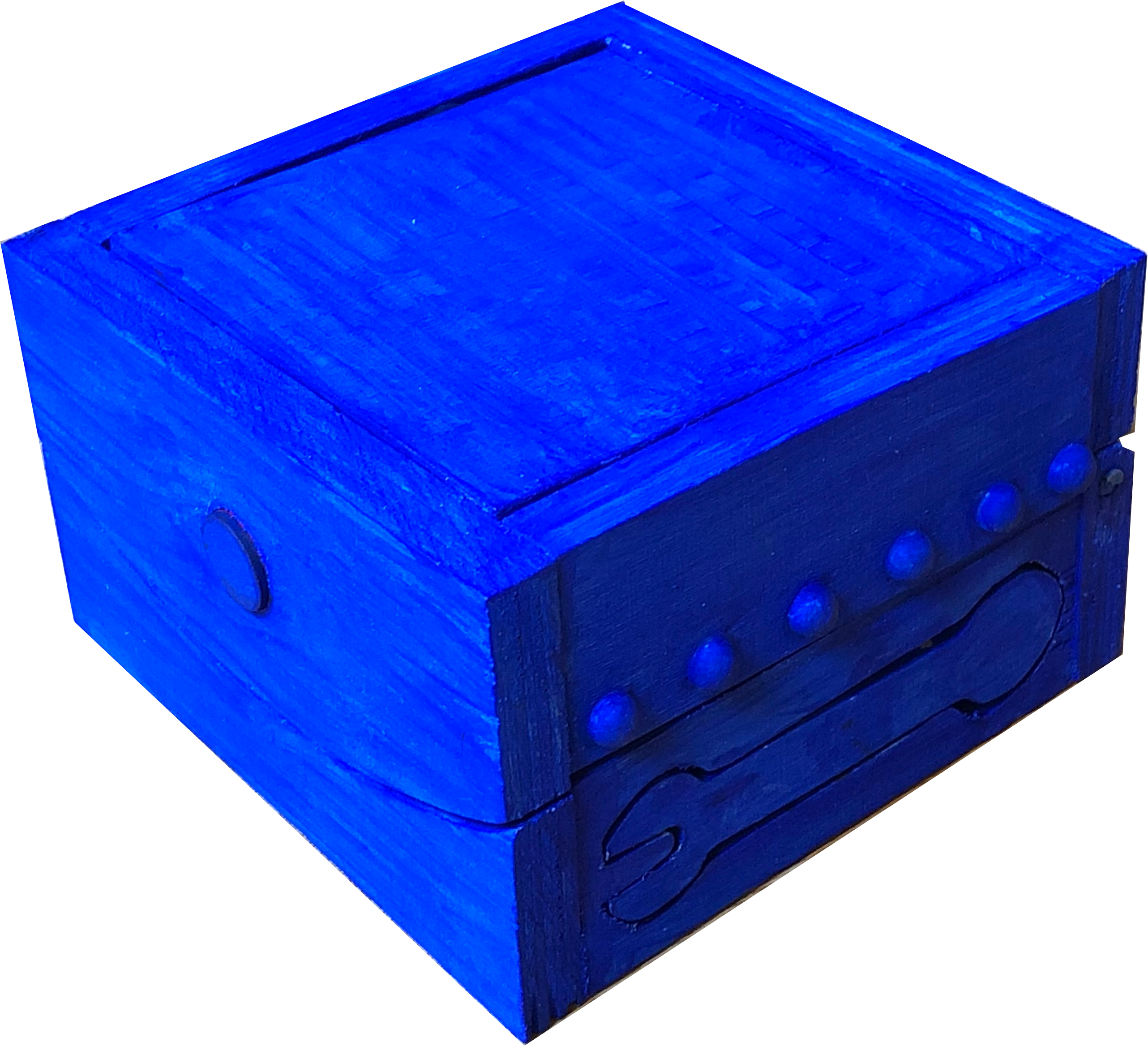
I wanted something friendly that wasn’t too complicated and something which initially looks like nothing special but which you can discover by pushing bits to see what happens. Best would be something to make you smile as things start to move. A sort of stringless desktop puppet, which reminded me that I always wanted to have a go at a pinocchio puppet with an extensible nose for when it starts telling lies. The hands should be useful but, for simplicity’s sake, should not have too many fingers so a spanner shape seemed just right. To make the nose extend, I made Blubot’s top tilt around its centre line, and a rod attached to the back of the top yields enough of a push to make the nose stick out. I even did a simple drawing to check that it would move far enough.
Drawing to check the clearance for the eyes and the movement of the nose
Making
This is basically a 10 x 10 x 8 cm box. The parts are cut from 10 mm plywood with a saw or a scroll saw for the curved bits. Good quality plywood means that the individual layers are properly glued and cutting doesn’t cause too much splintering.
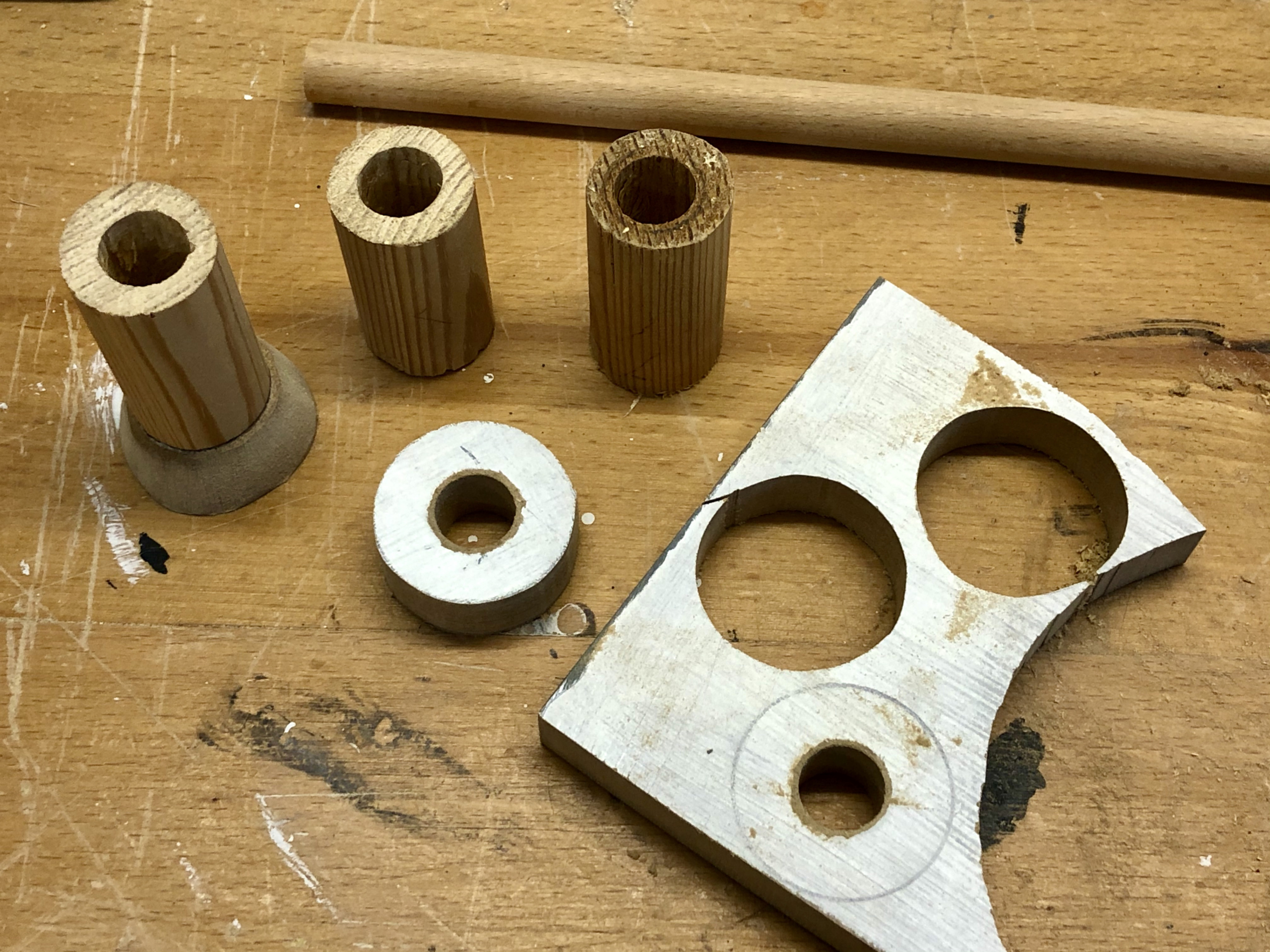
Parts for the box
The nose is a piece of 12 mm diameter dowel in a 13 mm hole. It was then handy to use a piece of the same 12 mm dowel to fix the nose linkage to the hinged lid. The linkage is a piece of 1.6 mm brass rod.
Top part of the box with eyes and nose
The nose linkage
I painted the eyes before gluing them in place and I glued a row of small hemispheres along both sides to make a sort of rivety impression.
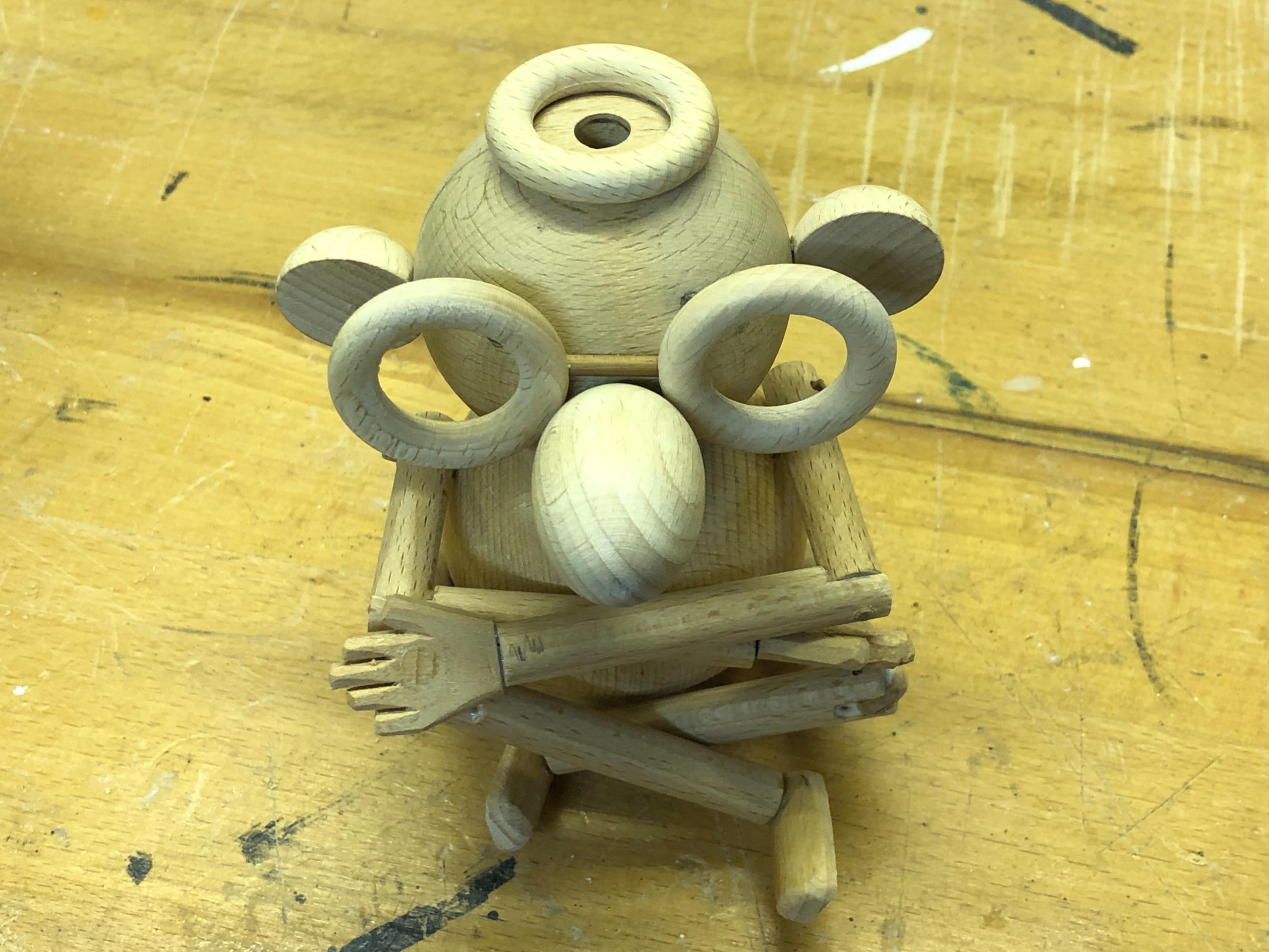
Initial version of Blubot
Addition to the design
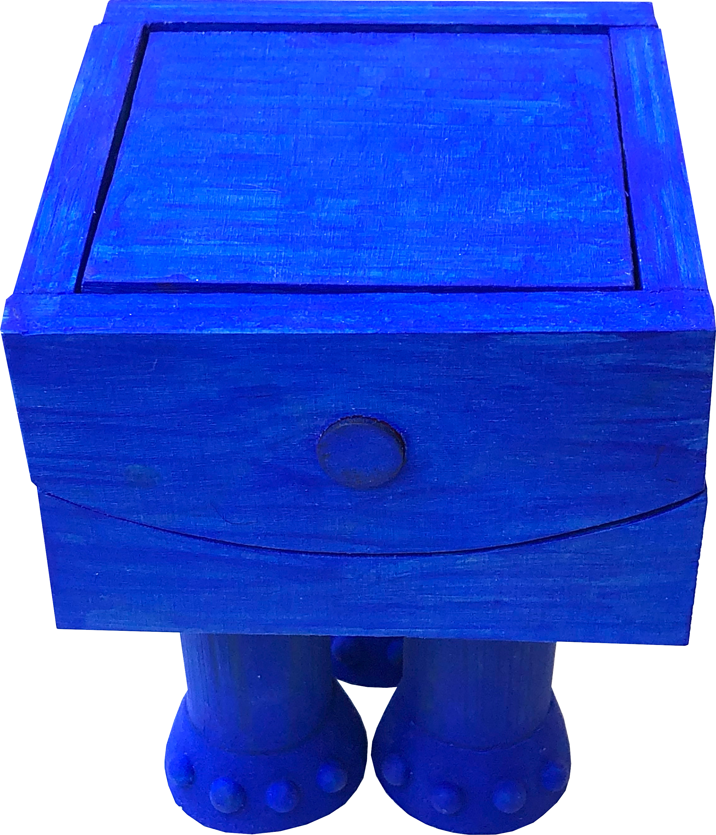
At this point I painted all of it and tried it out on my four-year old test pilot. More or less her first comment was that it has no legs. I had originally thought that legs wouldn’t add much to the narrative and might destabilise things. On reflection, I thought, OK well let’s add something moveable to the legs and decided on child-safe rocket flames, which come out on lift off. They just dangle on the string and disappear when you place the model on a flat surface, sliding back up into the legs.
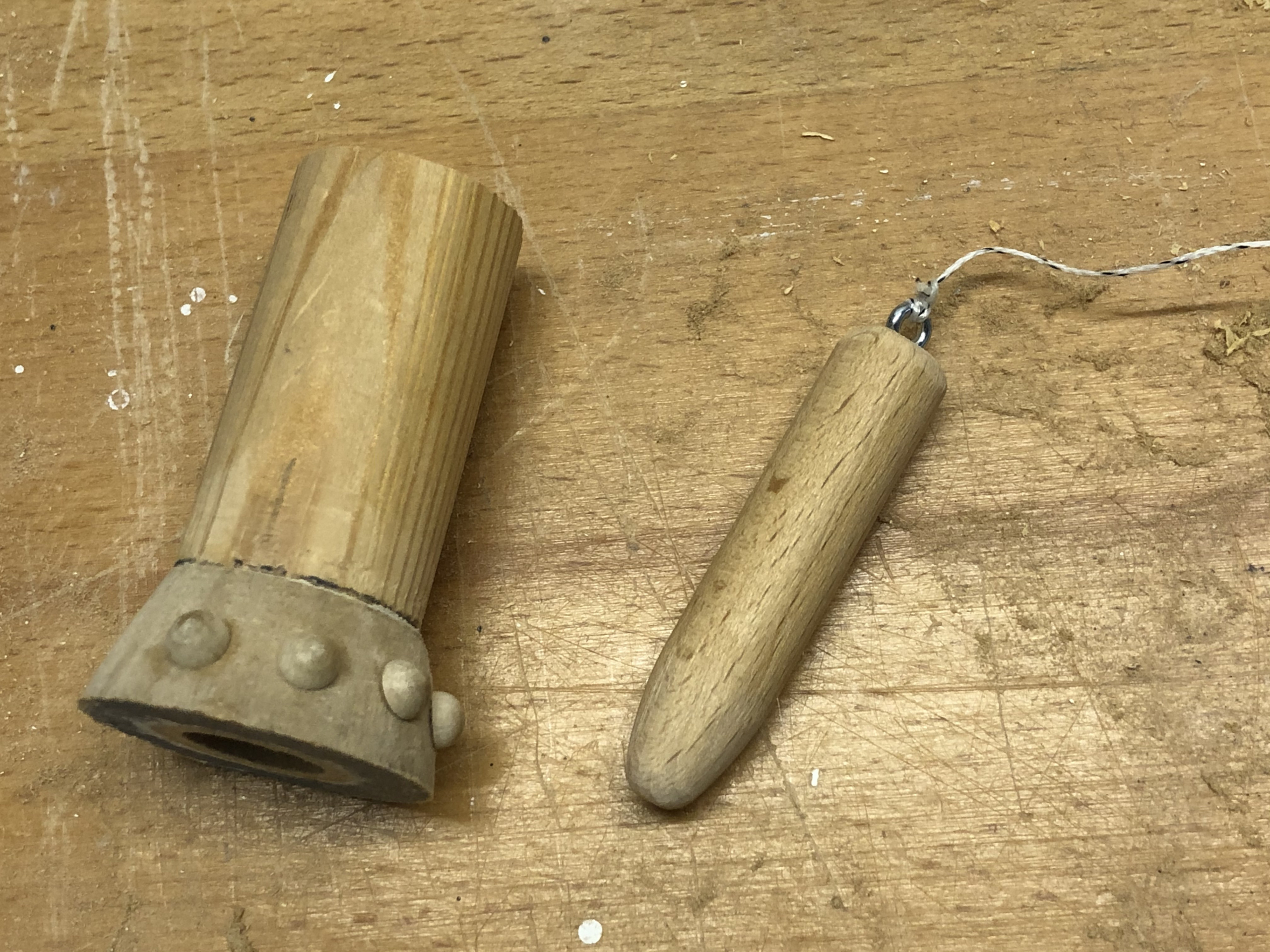
Making the legs and feet
For the feet, I used MDF, drilled a hole for the flame, used a bowsaw to cut a round shape and then sanded a taper. Continuing the rivet theme, I added 4 hemispheres to each foot which then look like toes, elephant’s toes!
The flame (right) slides out of the leg (left) and is retained by the string
I thus added three chunky legs, each with a hole drilled through the centre to accommodate the flames, each made of a piece of suitably shaped and painted dowel. Add a piece of string to prevent the flames from completely falling out and Bob’s your uncle!
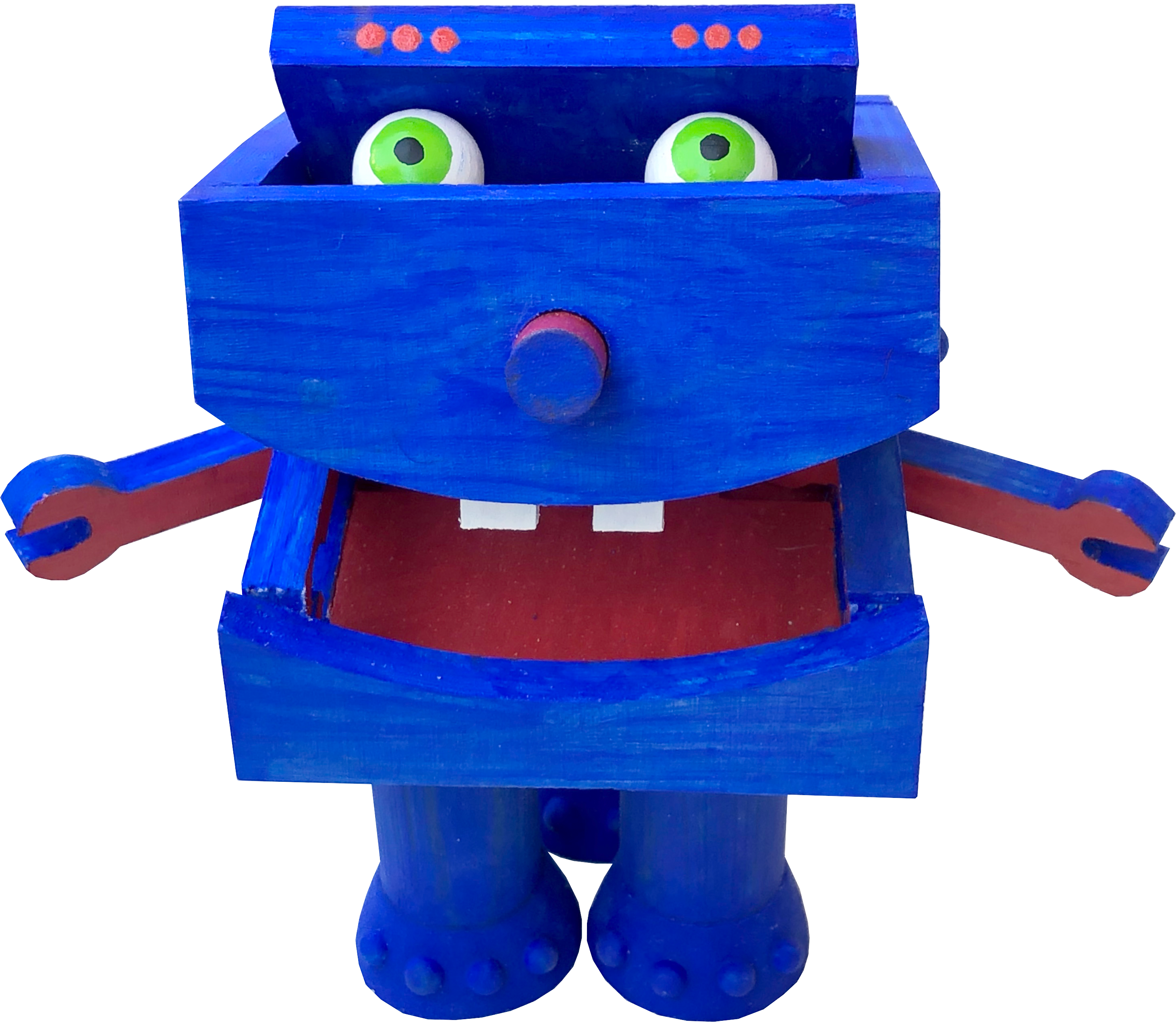
Lessons learned
It was good to work with better quality plywood than I sometimes do and I was very pleased with my simple wooden hinge at the back of the box. I generally find working with brass hinges quite hard work in such small items. Also, tilting the lid with two fingers to reveal the eyes and extend the nose gives you a very good level of control. Just right for puppeteering!
I find that the longer something takes, the more ideas that you have, don’t you? Even when you are painting, things can occur to you and it was only while painting that I thought of rivets for the eyebrows. 3D rivets were no good, as the lid wouldn’t close so I opted for nice painted red dots instead, which are the very first things to appear as you start tilting the lid. Almost the last things to appear are the two goofy teeth which is quite a funny climax to the opening of the box. I had originally planned on a full set of teeth, changing my mind at the last instant.
The flaming legs were quite simply an afterthought. It’s hard to imagine everything in your head right at the beginning. As things come together in reality, it is then easier to think a bit further and to grow your original idea.
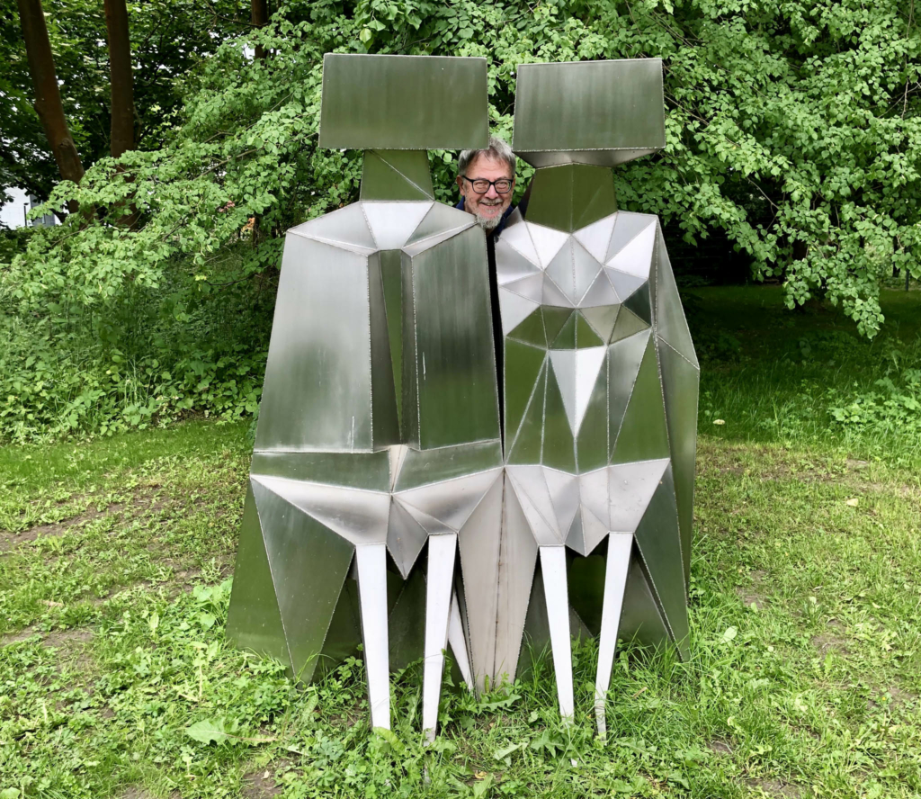
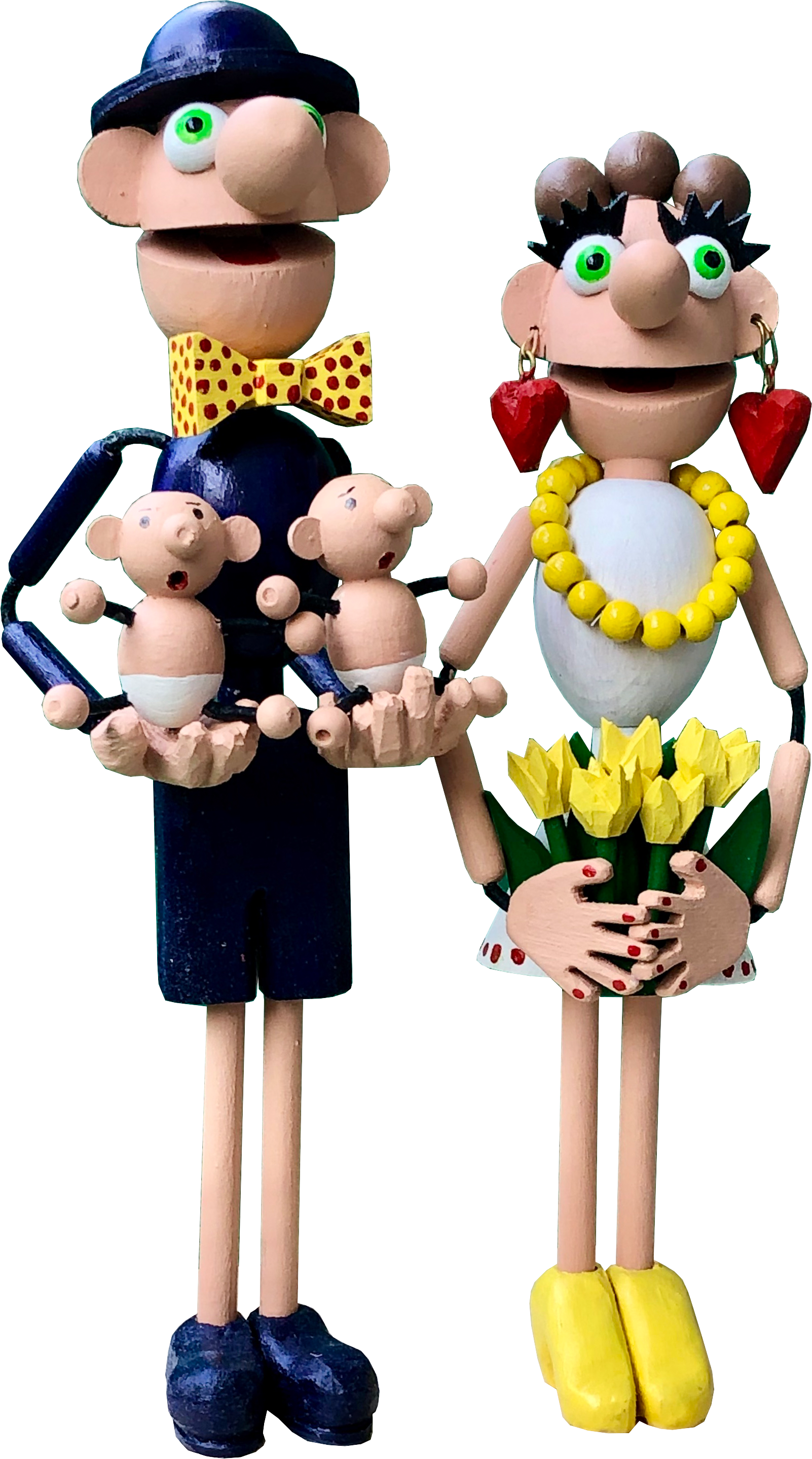
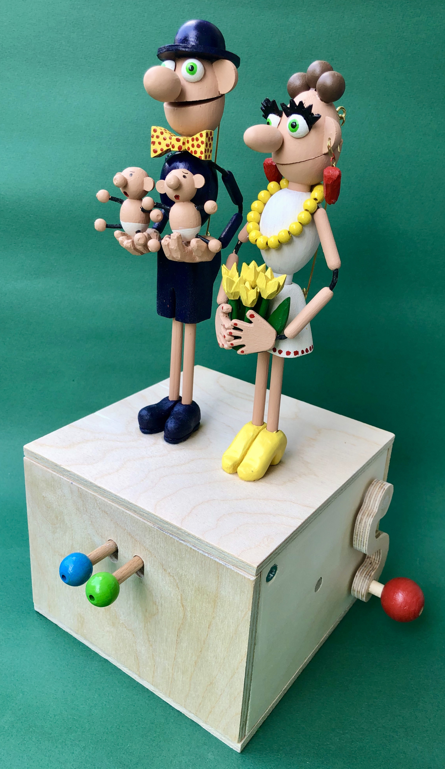
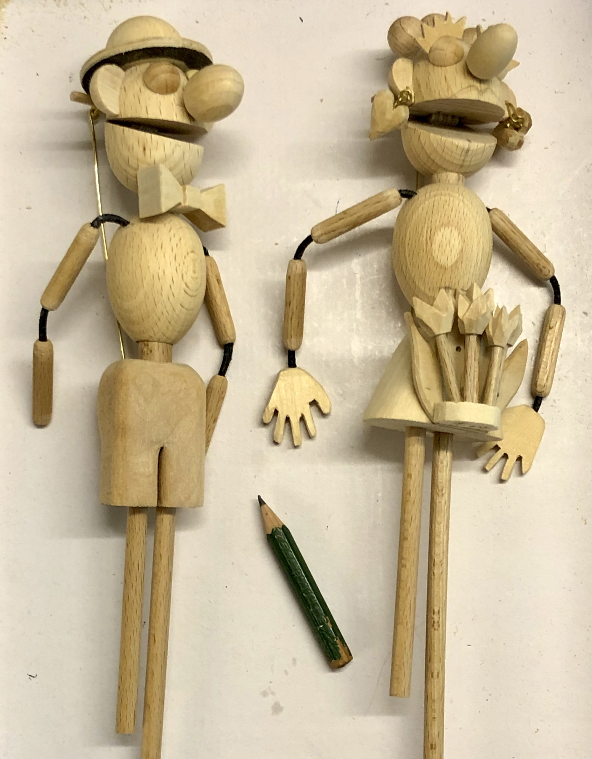
Happiness is infectious, so a happy couple must be doubly infectious, no bad thing to catch whatever else might be going around. The challenge is to move a happy couple into the fourth dimension so that they aren’t just in a happy state, they must also move happily too. I thought back to one of the United Kingdom’s prime ministers, Edward Heath, who was renowned for his heaving shoulders when he laughed, copied by many, not least by a later prime minister Theresa May (see https://www.youtube.com/watch?v=U_wGgPvoysQ).
Our happy couple are also confronted with the eternal question of what to do with your hands whilst on the podium. I decided to have the woman hold a cheerful bunch of flowers, in her personal colour scheme. For the man, another, smaller happy couple seemed just right, even if children have their own ideas about when to be happy or not.
Technical brief
My test engineer, a very smart 4 year old girl is so entranced by talking figures that she likes to not just follow the programme set by the cams, she likes to improvise too, inventing her own narrative about what is happening. This often means grabbing brass rods and yanking them to achieve her desired effect. In this automaton I thought that it might be smart to anticipate that and offer two ways to bring our cameo scene to life. A red handle turned on the side gets the cams moving stubbornly through their preprogrammed sequence and blue and green levers on the front allow free improvisation.
With the blue lever, the man can chatter or laugh endlessly, while his partner waits patiently. With the green lever the woman can return the compliment, while he listens attentively. Of course both can join in the action as and when they wish.
This means that a logical OR function is needed. The shoulders lift and the mouth opens if the red lever is turned OR if one of the blue of green levers is pressed. This means that if the red lever has opened a mouth, pressing the corresponding blue or green lever will have no effect. Blue or green can only do their thing if the red lever is in a passive position which would leave the corresponding mouth closed.
Cranking the red lever turns two cams, one with eight regularly spaced movements, the other with nine. This means that the two figures laugh together, but they are not synchronous, making a pleasantly chaotic impression.
Making
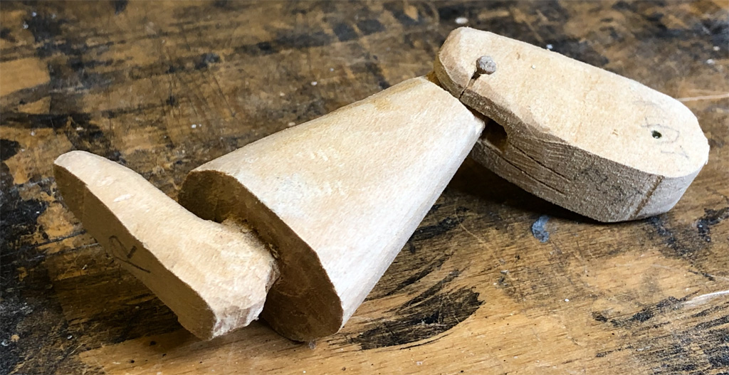
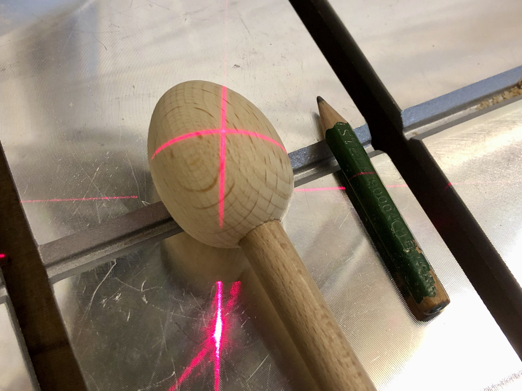
The heads are made from hardwood (beech) eggs which are cut through diagonally at a smiley sort of angle. There are a few tips for a successful cut. (1) It’s tricky to clamp an egg and then cut through it, so it helps if you first drill a hole in the end of the egg and then glue in a dowel. Now you can clamp the dowel, leaving the egg freely accessible for your saw. (2) My drill press produces two sparkly red laser lines which cross to show the position of the centre of the drill bit. If your drill has this feature too, it’s very handy to mark a “straight” line on an egg for cutting. (3) Drill the hole for the jaw hinge before cutting.
How to mark & cut hardwood eggs
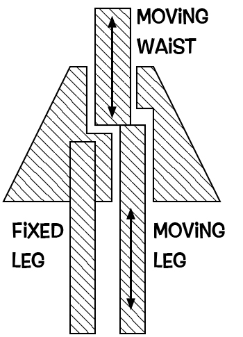
The figures’ movement
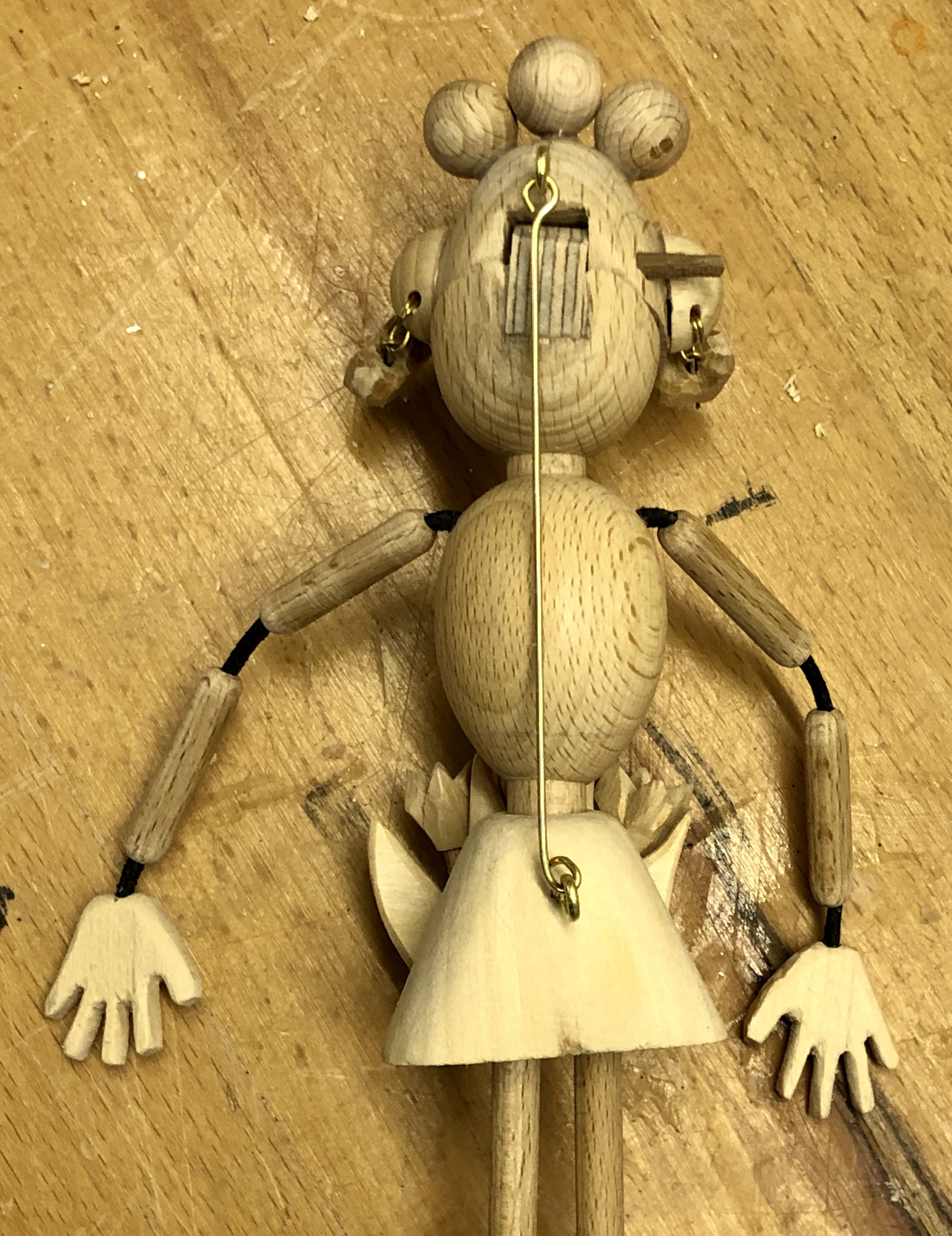
The two figures’ movement is controlled in the same way. In this simplified section through the woman’s lower body you can see that one leg is fixed to the body (and to the base). The other leg moves up and down, which is not obvious to the casual viewer, pushing the waist and the upper body up and then allowing it to fall down.
Simplified section through the women’s lower body
The top of each head is attached by a brass rod to the lower part of the body. When the waist is pushed up this cause the rod to pull the mouth open. I used an old leather shoelace for the shoulder, elbow and wrist joints, allowing them to move quite freely.
Leather shoelace for the joints
Top of head is attached by a brass rod to the lower part of the body
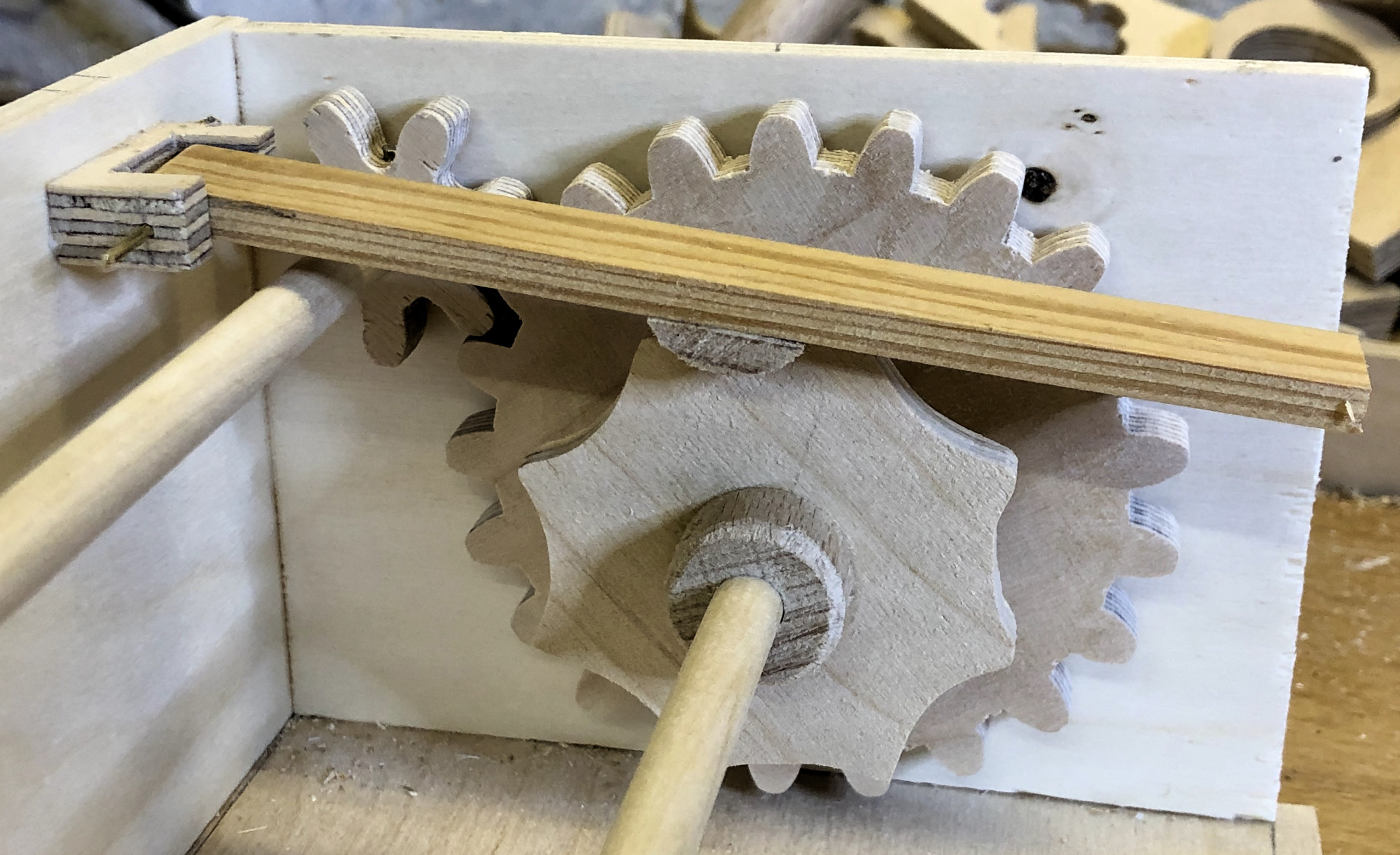
The works inside the box
Turning the red handle rotates a small cog which drives a larger cog. This gearing makes it easy to turn and the outside lever is as long as possible to provide the best “leverage”. The larger cog is attached to the same shaft as the two cams which each drive a simple cam follower.
The geared drive for the cam with 8 curves. The other cam has 9 curves.
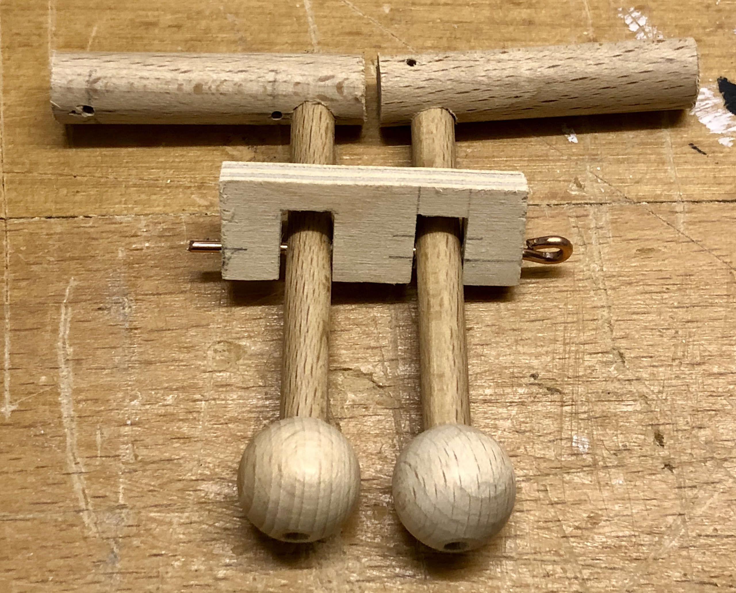
Pressing the blue or the green lever simply lifts one of the cam followers. At rest, the weight of the inside parts moves the outside knobs up into their inactive positions.
The blue and green levers
With slots cut in the front panel to allow the levers to move, the complete mechanism looks like this. Now you can see that each cam follower can either be lifted by the turning cam OR by pressing the lever at the front of the box (at the right in the picture).
The complete mechanism with two alternative ways to lift each cam follower
Note that if the cams are lifting the followers, then the blue and green levers will have little if any effect. You can’t lift something that has already been lifted.
I painted the parts for the figures prior to assembly and allowed them to dry properly to ensure that I got the clearances right for easy movement. The babies are very simply made and don’t move, their tiny fists and feet represented by small spheres.
There was an old spider who lived in quite a stew.
She had so many children, she didn’t know what to do.
So she span a nice roundabout from silken thread;
And whizzed them all around until she put them to bed.
Mum spider was worried about the kids just hanging about and wondered what she could do to keep them busy.
Then she saw this bare tree and thought this will do nicely.
With a little bit of work, there’ll be room for everyone.
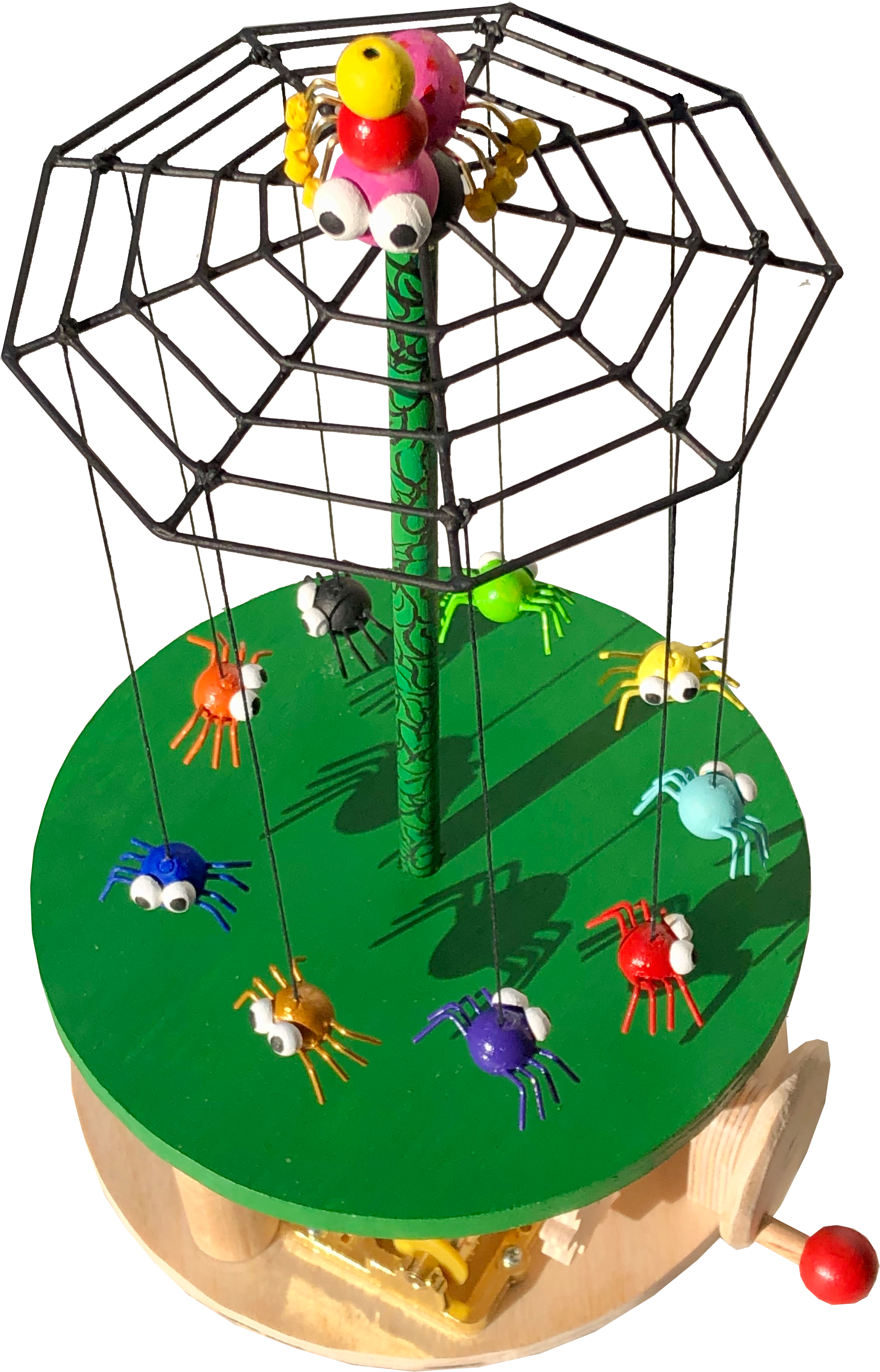
The technical brief
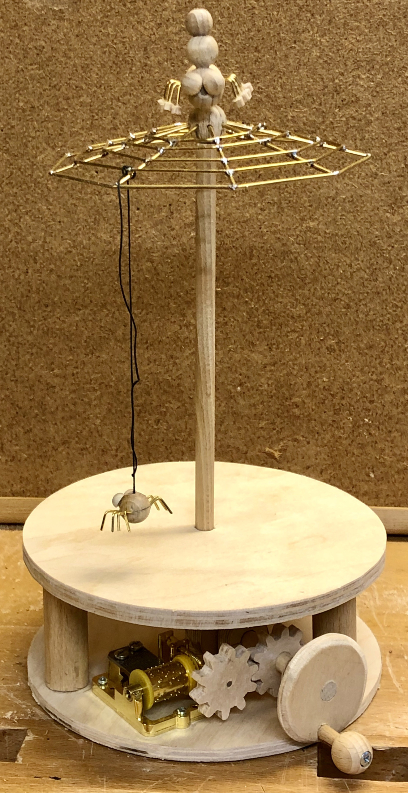
The mechanism to turn the roundabout should be as simple as possible and should also drive a small music box mechanism which plays “Die Berliner Luft” – a tune that every Berliner knows about Berlin’s fantastic air. Spiders can have phenomenally large families, but I decided to go for a token number of nine baby spiders. What was good enough for Queen Victoria and Prince Albert is good enough for me. They had four boys and five girls, I will leave it to the viewer to decide on the sex of the various members of my little family. Brass rods will be strong enough to make the web and wood will do for the rest.
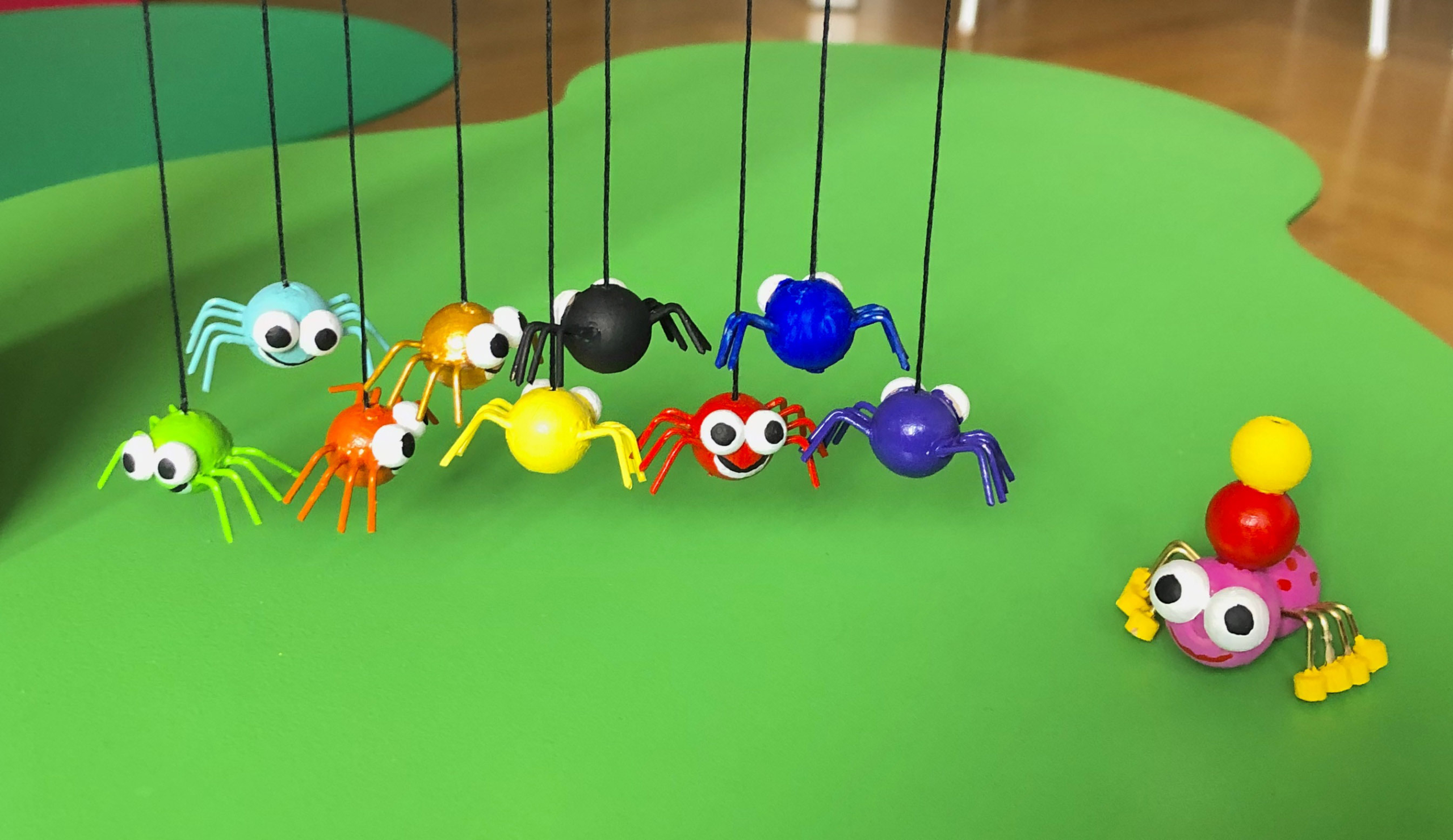
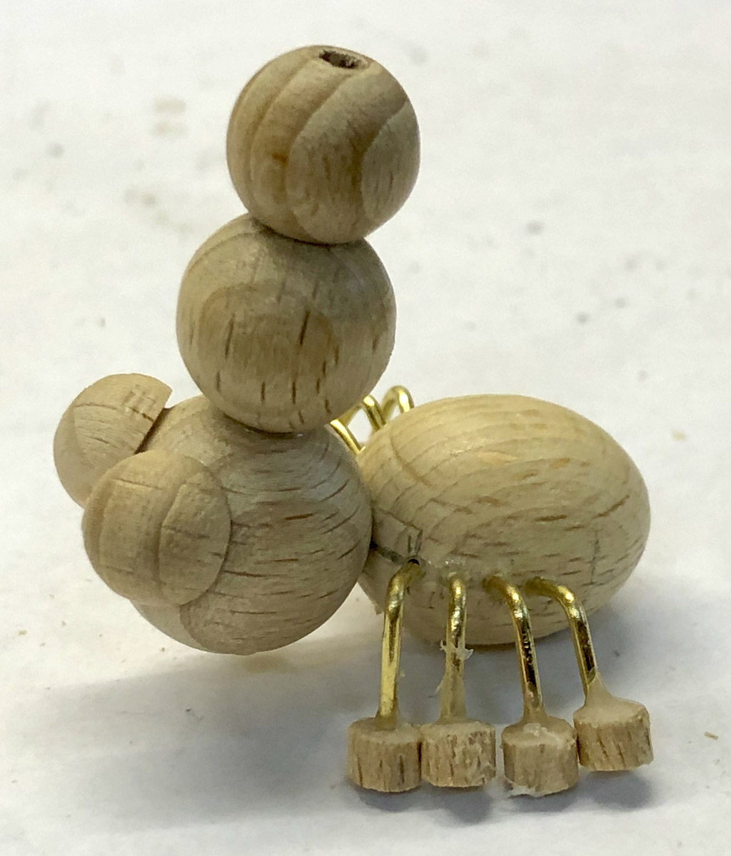
Making the family
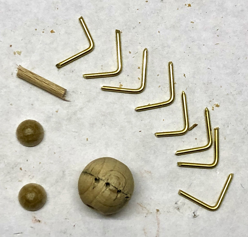
The parts to make a baby spider
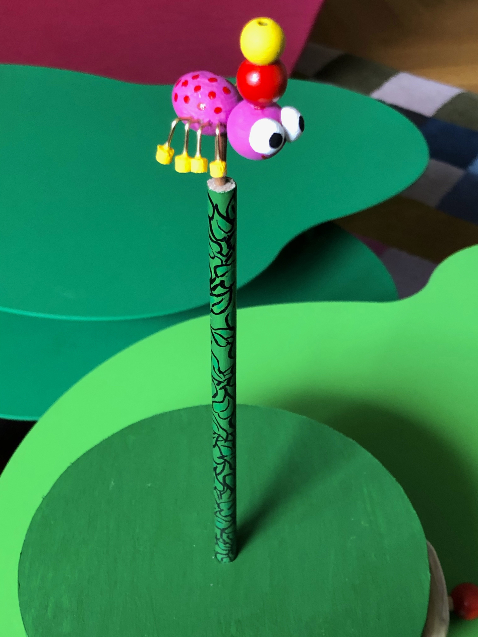
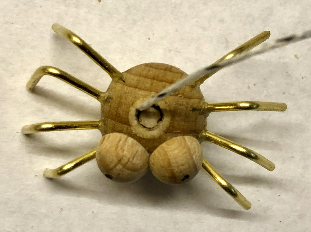
Baby spiders are uncomplicated creatures made of a small drilled wooden ball for the body, two wooden hemispheres for big appealing eyes and eight pieces of bent brass rod for the legs. For the strand of web for them to dangle from, I used a cotton thread glued into the predrilled hole which I then filled with a piece of 3 mm dowel.
Finished baby spider waiting for its colour
Fashion-conscious mum spider
Mum spider is larger of course, has a more stylish hairdo and shoes and a 3 mm hole in her underside to attach her to the top of the tree.
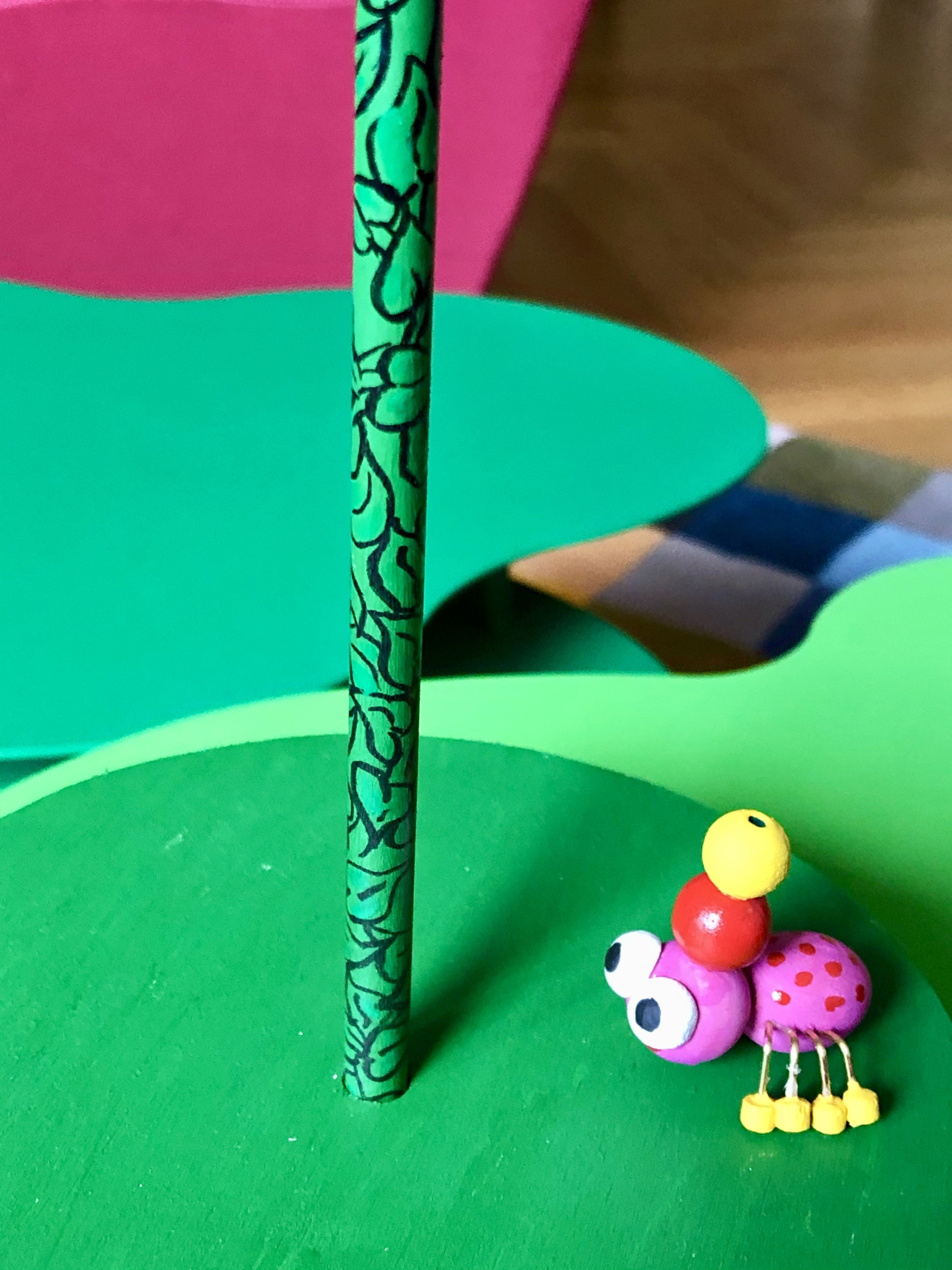
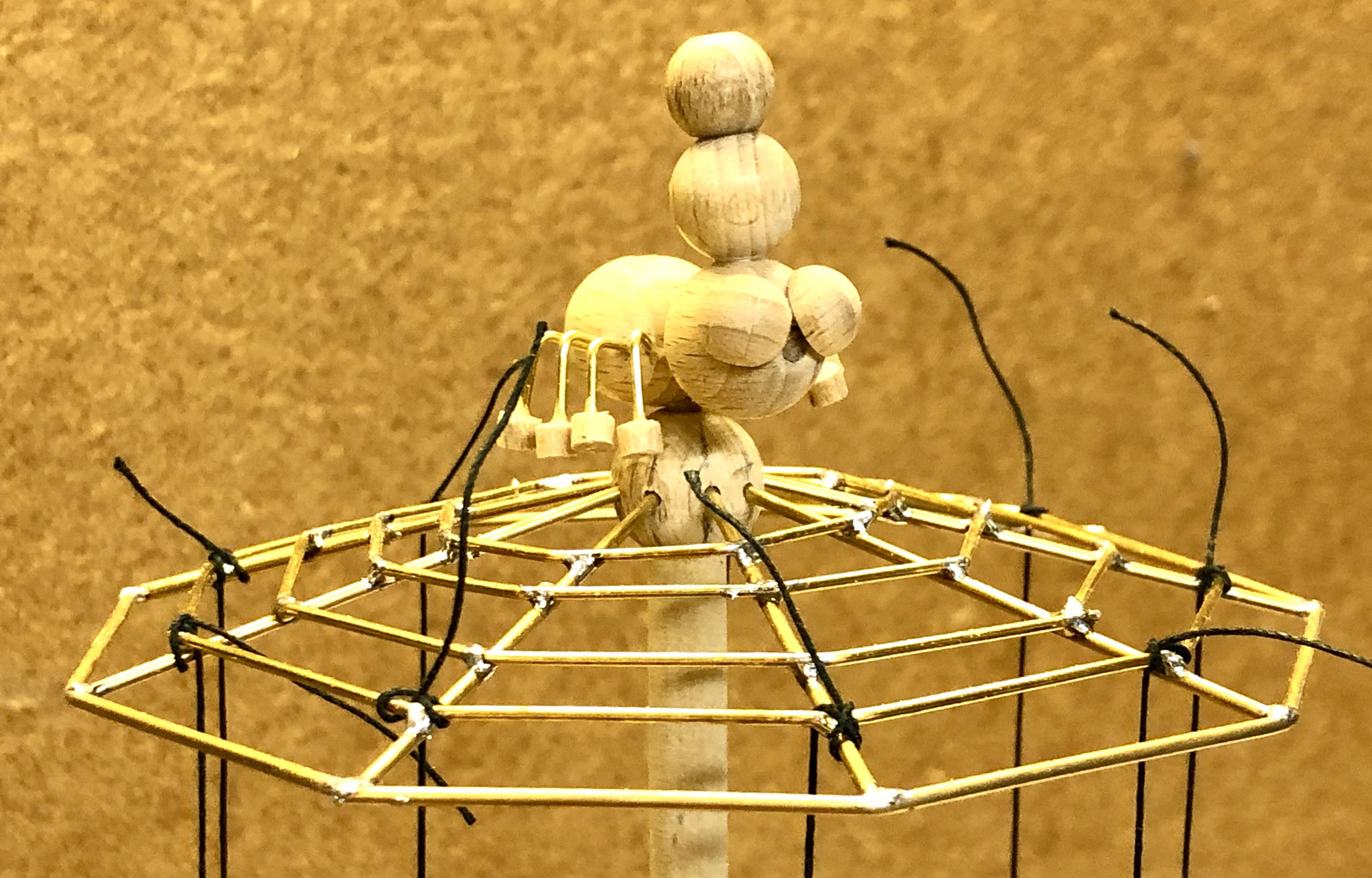
The web
Spider mum and her freshly spun web
As there are nine spider children, the web has to have 9 segments. Mum spider needed a bit of help to make the web so I used slim brass rods, bent carefully to shape which I then soldered together, arranging for a slight “umbrella” shape. The web is mounted into a wooden ball which just rests on top of the tree, with a 3 mm dowel through the middle to hold mum spider, glued safely in position. As the ball is not glued, it is turned by friction. This allows mum to jig around and issue instructions to her brood and also allows the web to coast gracefully to a stop when the tree stops turning.
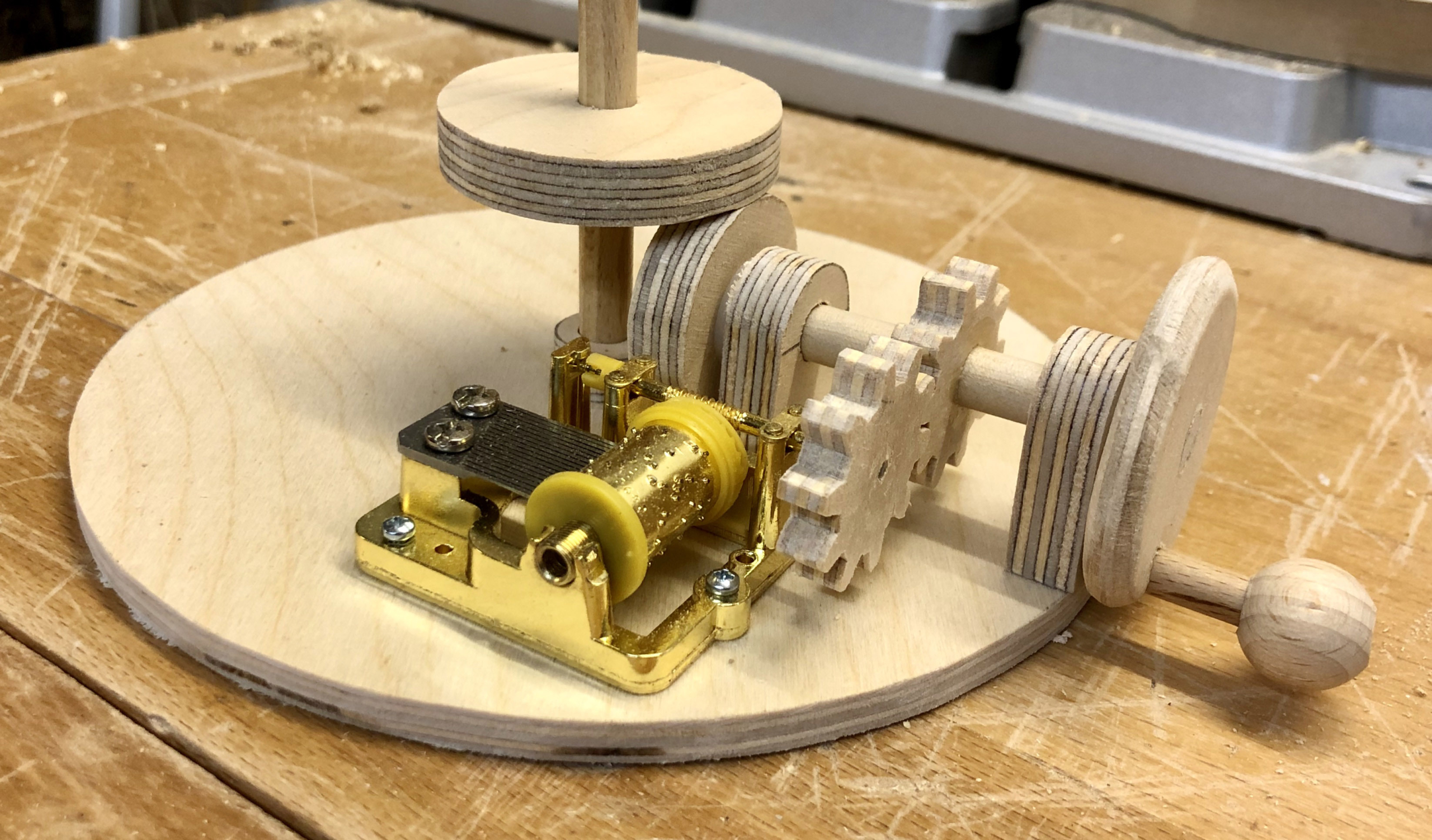
The base mechanism
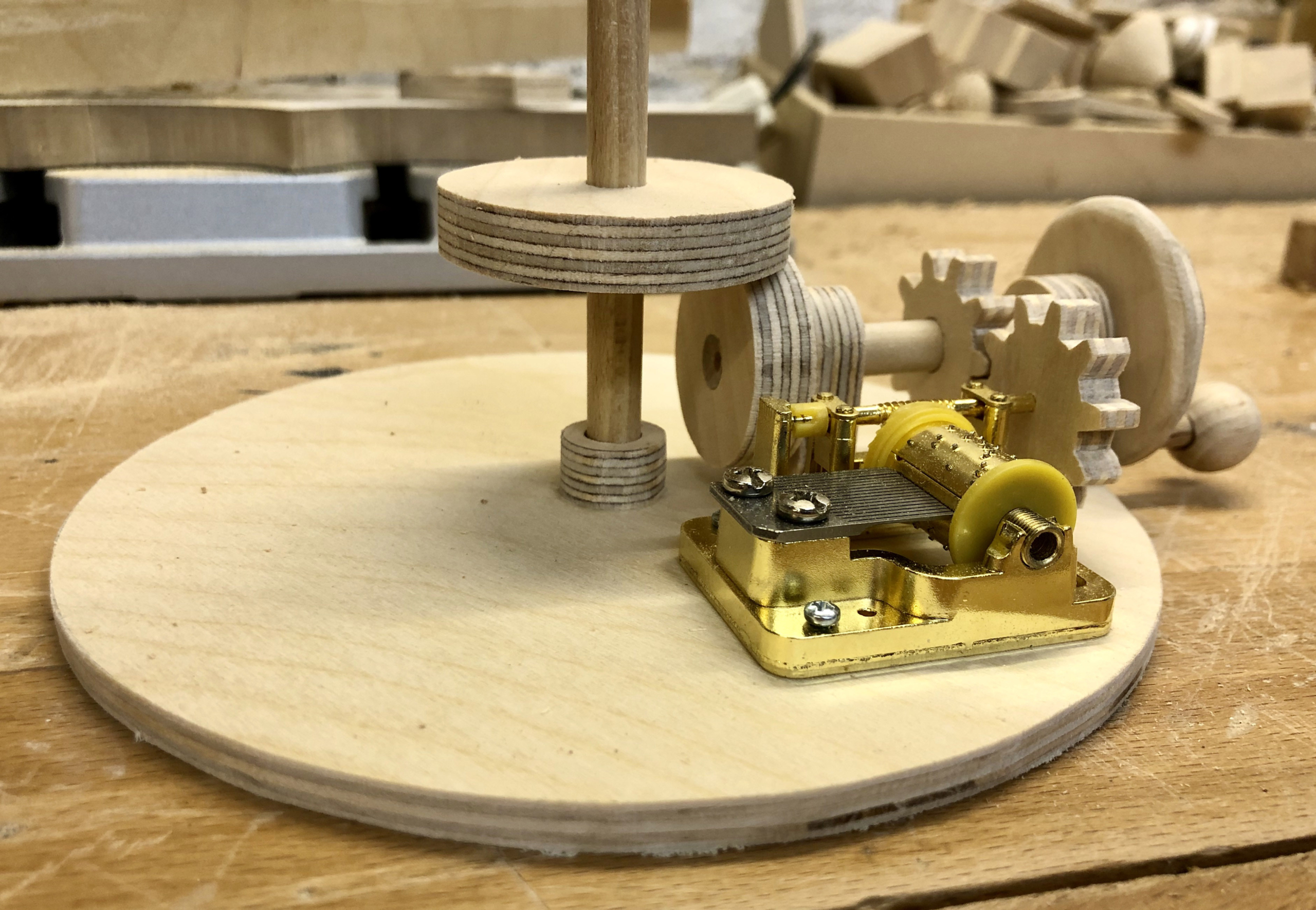
The bare mechanism
On a circular base, I mounted the small music box mechanism which I bought for a few euros. After cutting its bent metal handle off, I could push on a wooden cog which I cut using my bow saw. An identical cog drives it, when the handle is turned. Fortunately the music mechanism doesn’t mind if you turn it the wrong way, it just goes click, click instead of playing its merry tune. Turning the handle also rotates the drive wheel which is in frictional contact with the larger wheel glued to the vertical “tree”. I added a wooden bearing at the base of the tree which, together with the hole in the upper part of the base, keeps the tree nicely vertical.
The assembled roundabout, ready for testing
The upper part of the base rests on three fairly chunky pieces of dowel. Careful alignment is required to ensure free rotation of the tree before gluing things together.
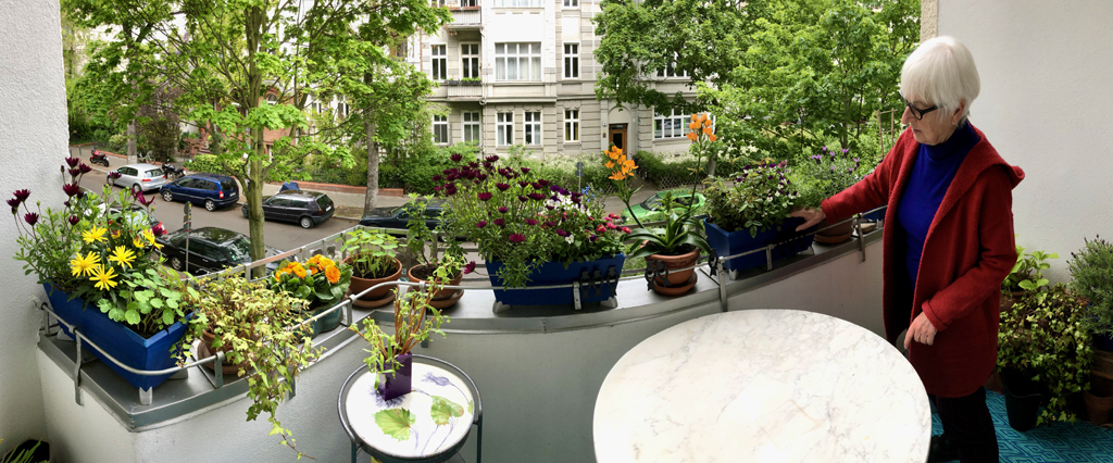
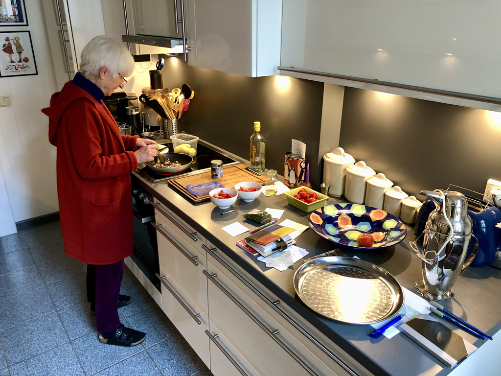
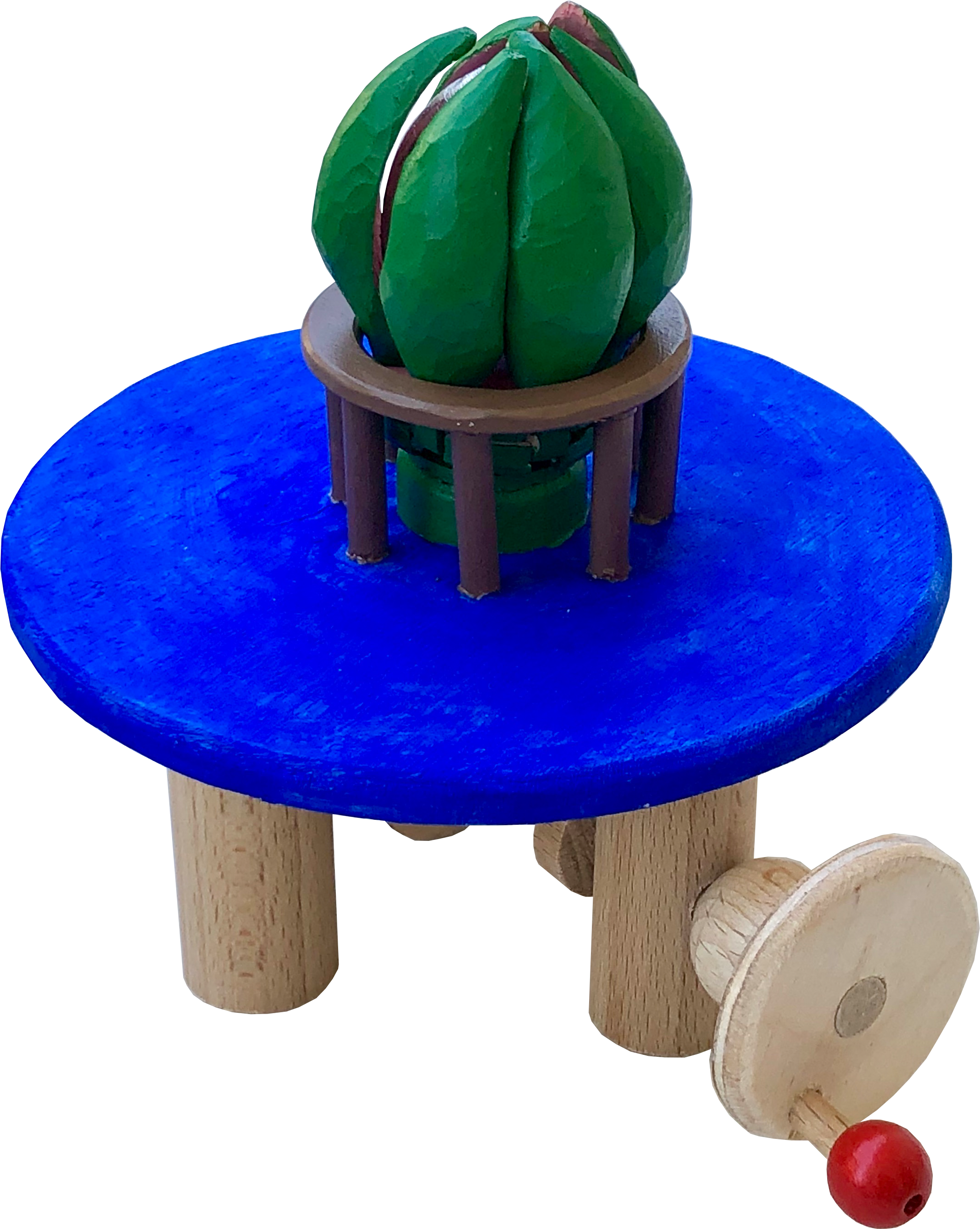
Summer is a cumin in Berlin and my wife is busy planting the balcony so that we can enjoy our evening cocktails in a fragrant, colourful environment. Young plants grown in Dutch greenhouses do give you a really quick start but much patience is still required. As an impatient man, I thought about what I could conjure up that gives instant satisfaction for friends of the floral.
The technical brief
The mechanism was to be as simple as possible. A handle rotates a cam which friction drives a wheel perpendicular to it, so that the wheel and its shaft are both lifted up and down and rotated a little. Petals are attached to the other end of the shaft and as the shaft is lifted, the petals should open up to reveal an egg-shaped centre.
Petals & hinge
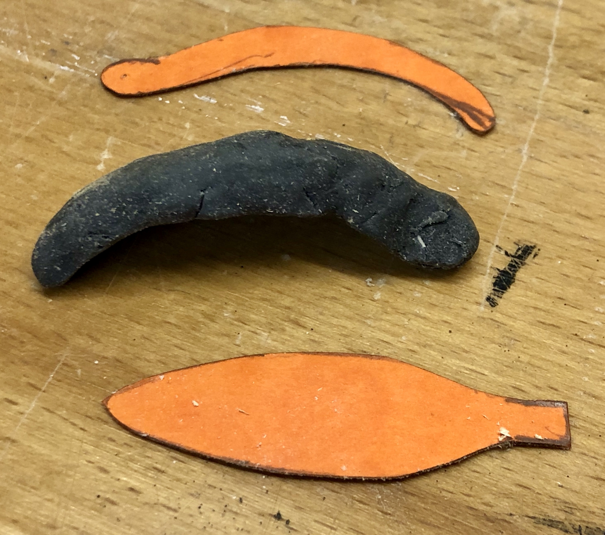
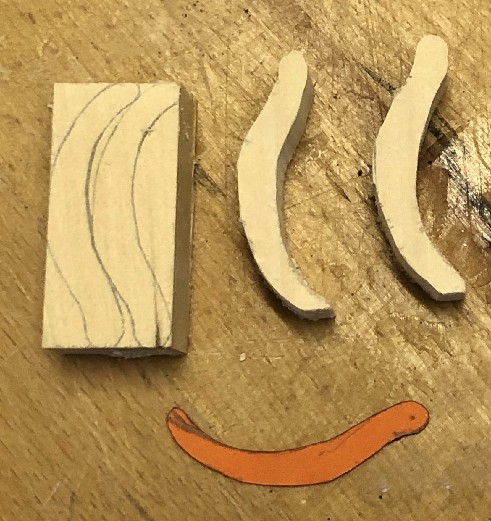
To get the shape of a petal I used a piece of plastercine pushed against a wooden egg. From this I made two templates in card, to mark up my lime wood for cutting on a bowsaw.
Plastercine petal and two card templates
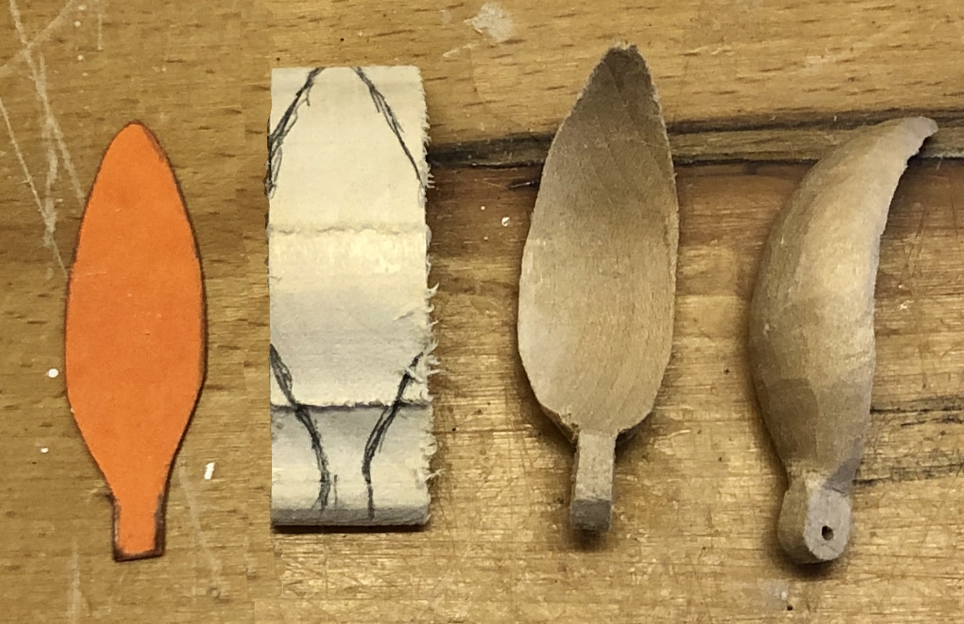
First cut for petals
Second cut and carving for petals
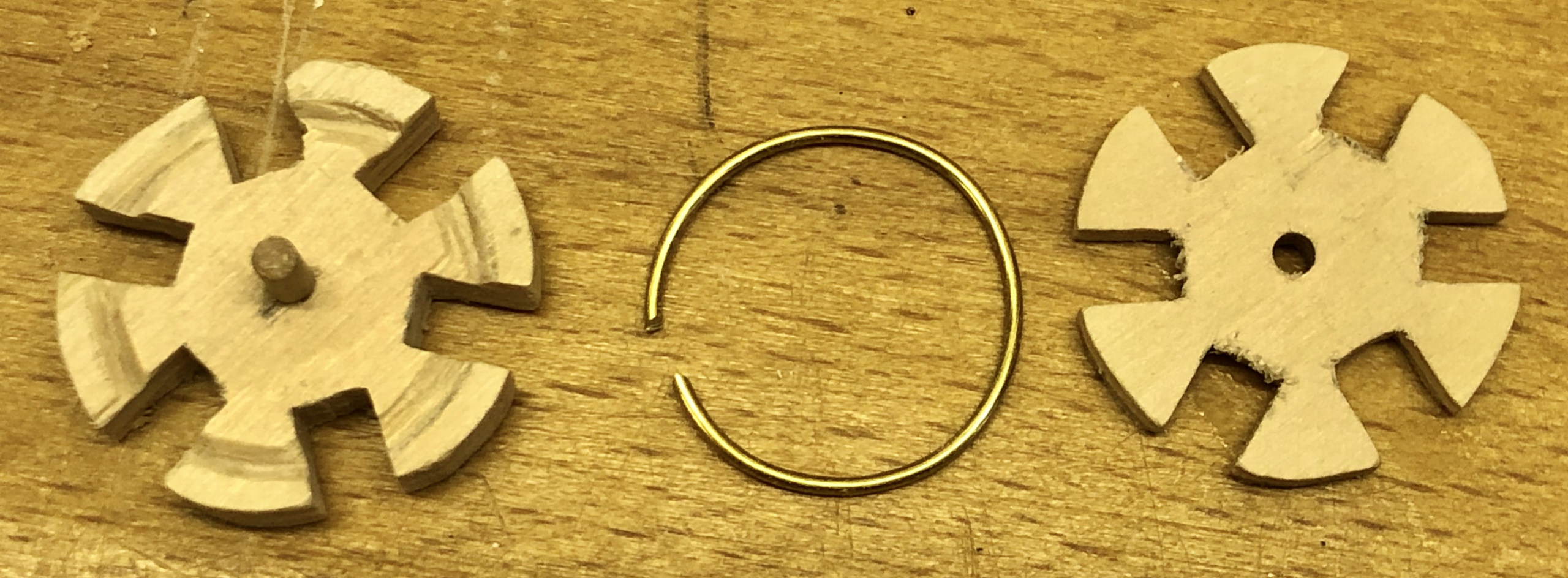
Instead of trying to hinge each petal separately, I bent a piece of brass rod into a ring and cut two holders to grab the ring in a sandwich.
A hinge for 6 petals
And when this is all assembled it looks like this
6 petals hinged on a centre piece
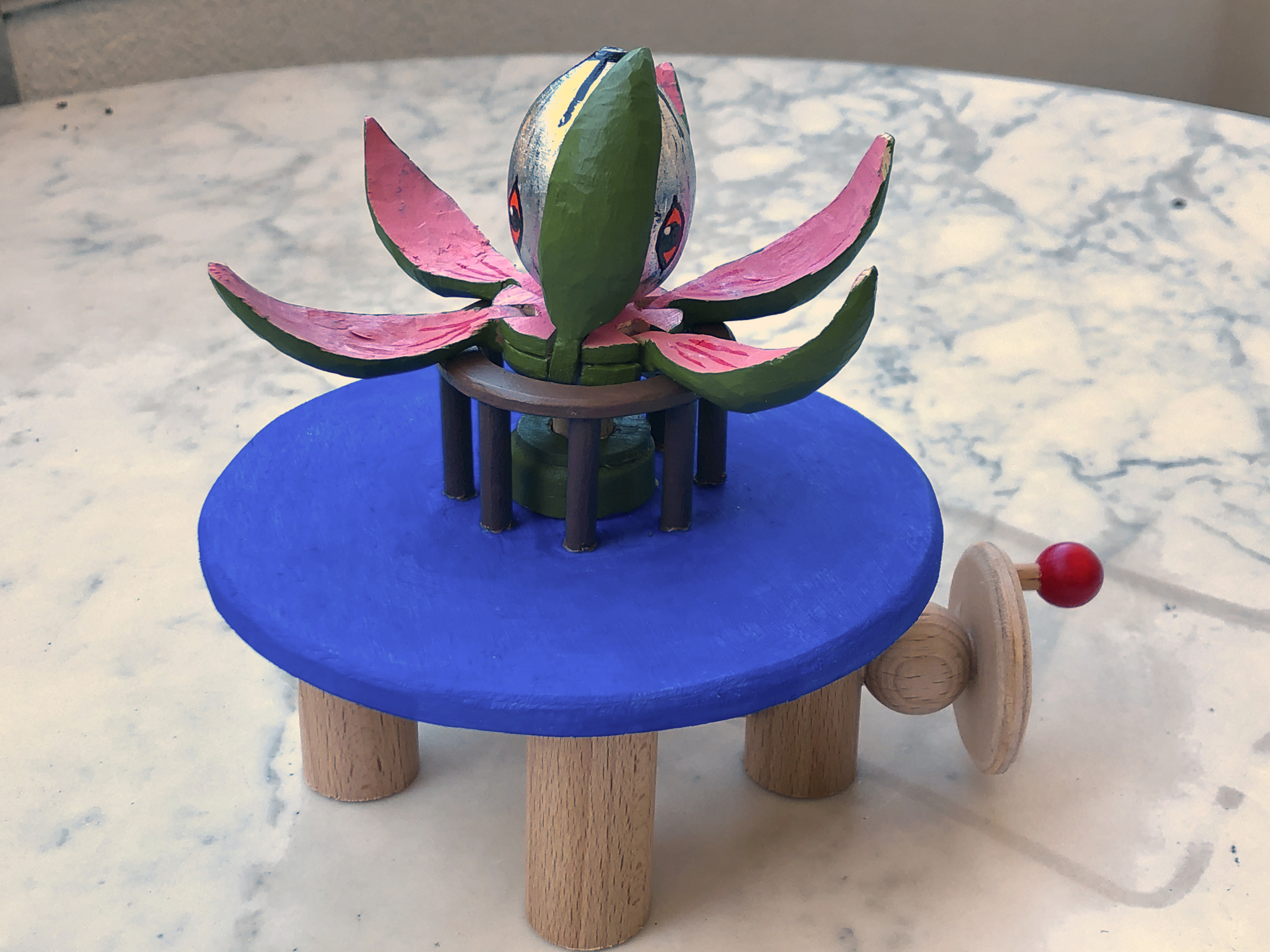
The base mechanism
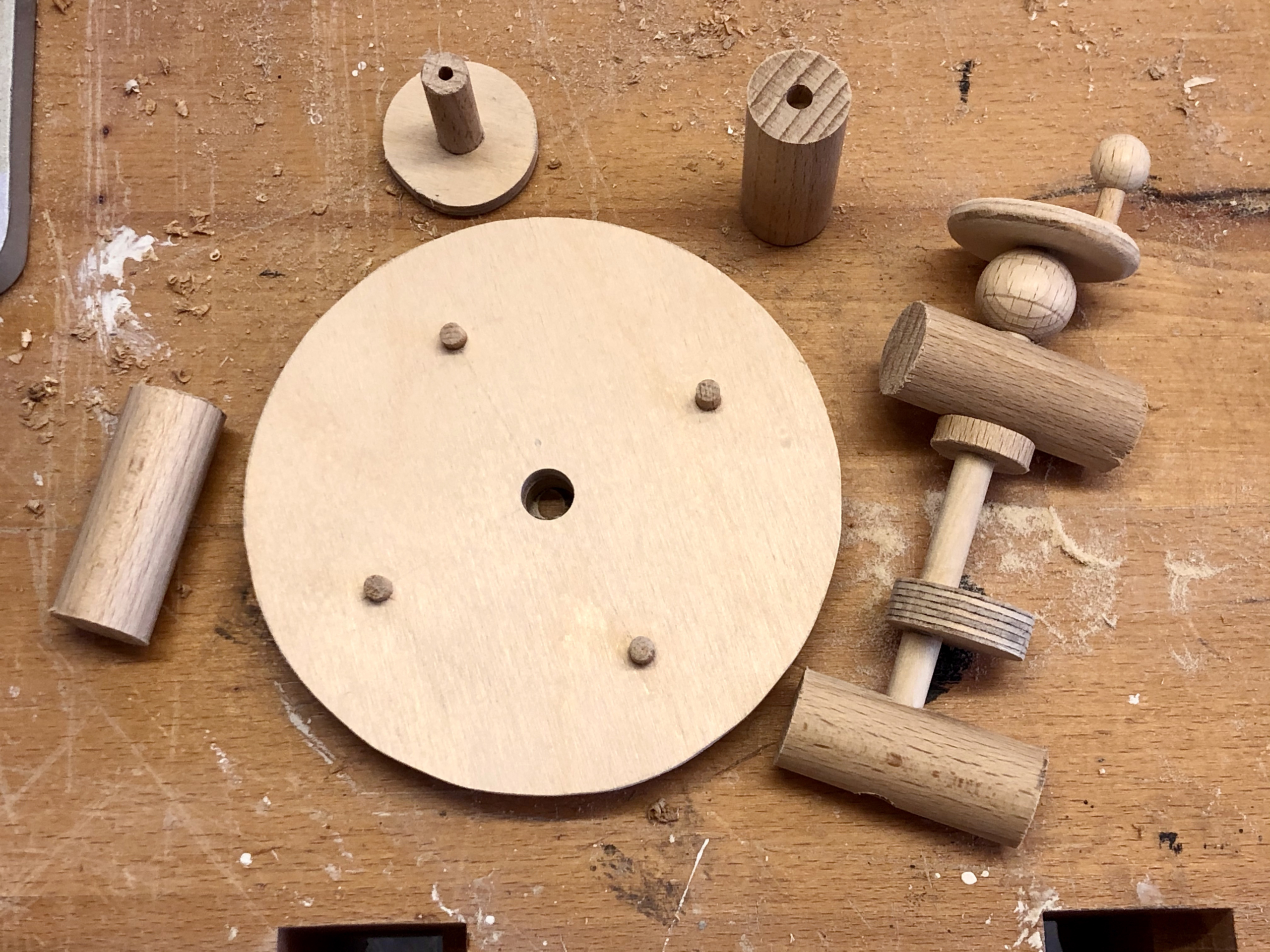
The base has four chunky dowel legs. Two of the legs have holes to take the 8mm dowel axle with its cam and its disc-shaped crank
Parts for the base mechanism
The assembled base mechanism
There is a short video showing the effect of turning the crank.
Youtube link “https://www.youtube.com/watch?v=gQMXmhIrygE”
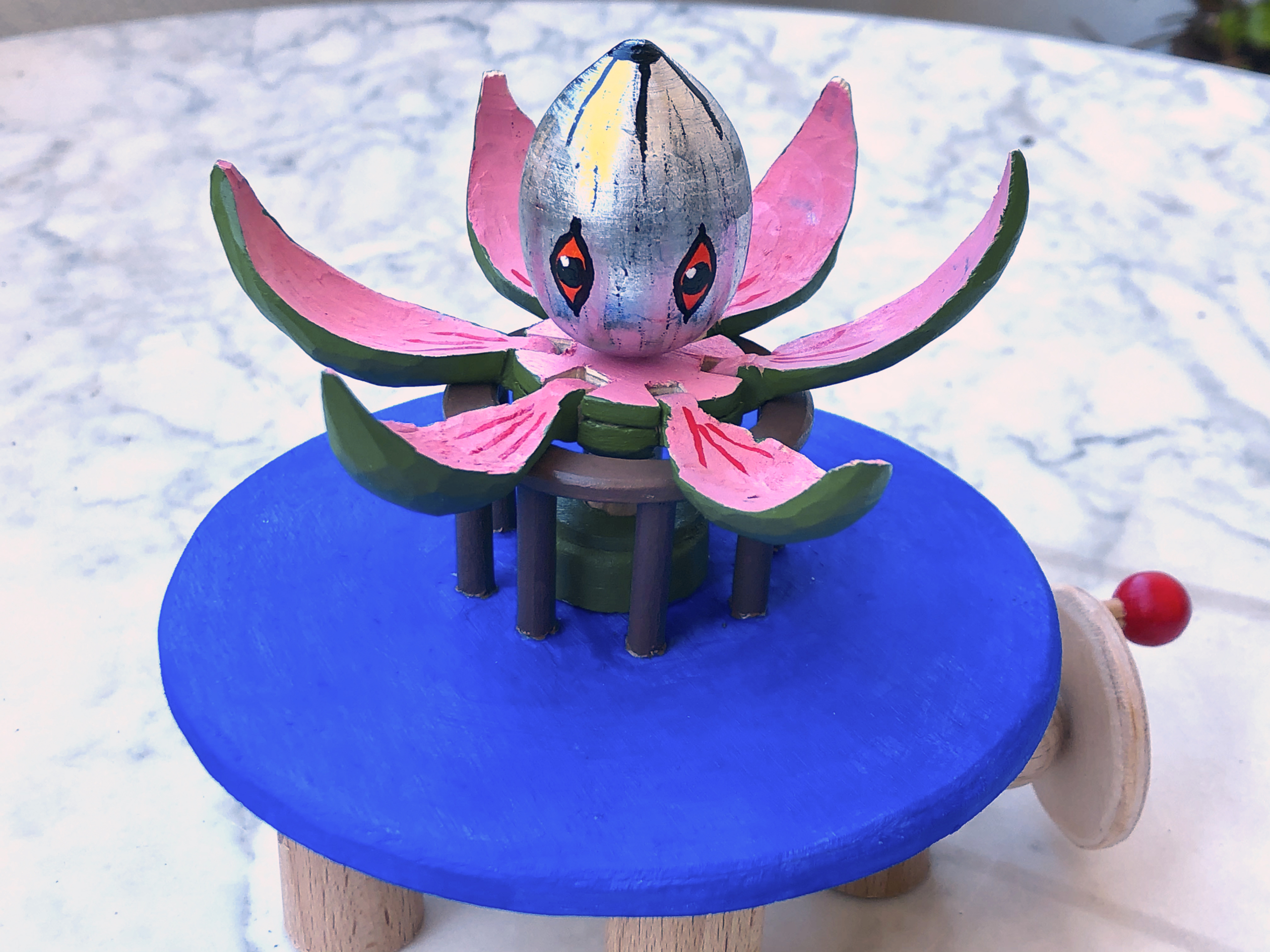
The flower and its “cage”
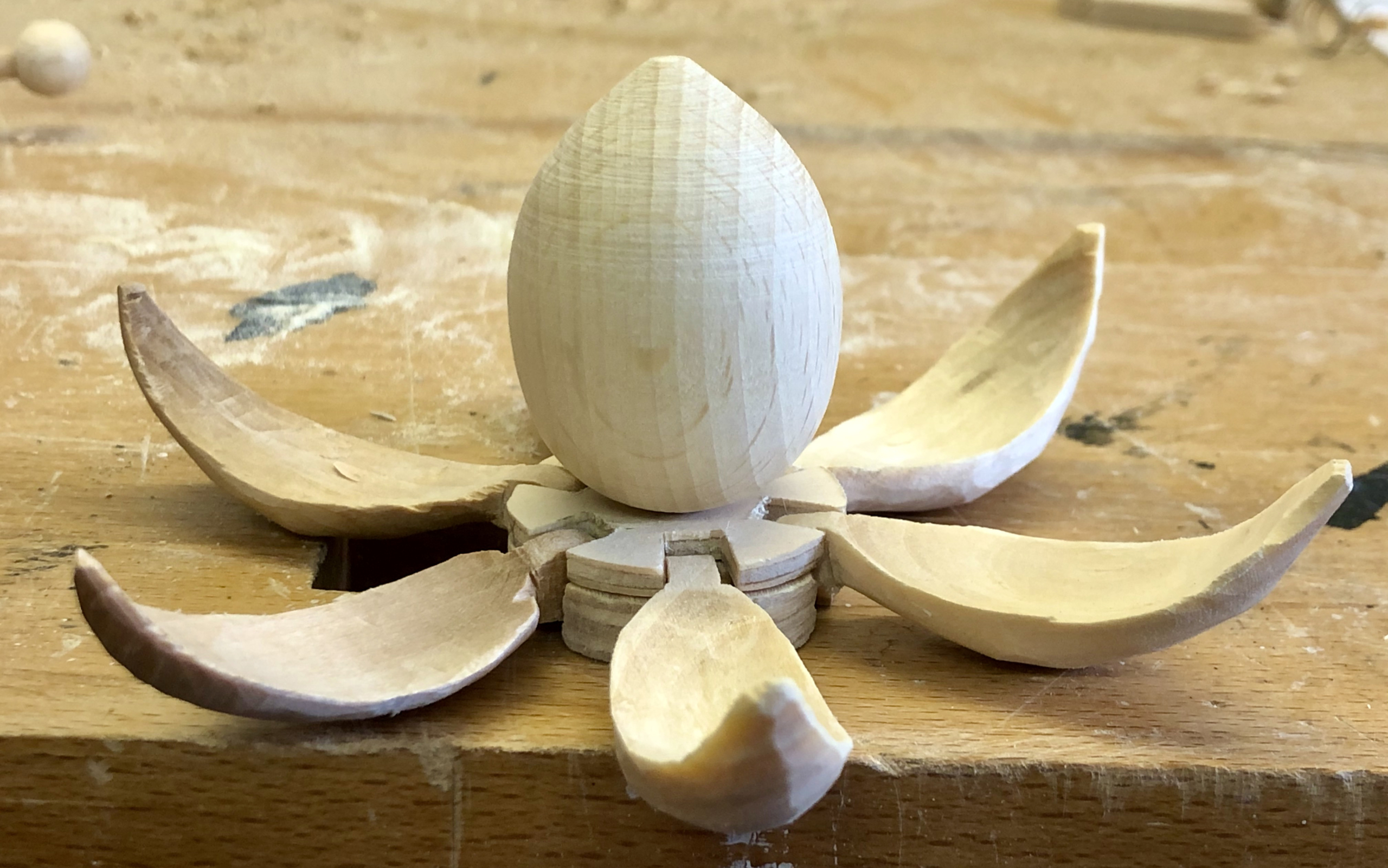
Adding a wooden egg into the centre of the petals completes the flower
The open flower
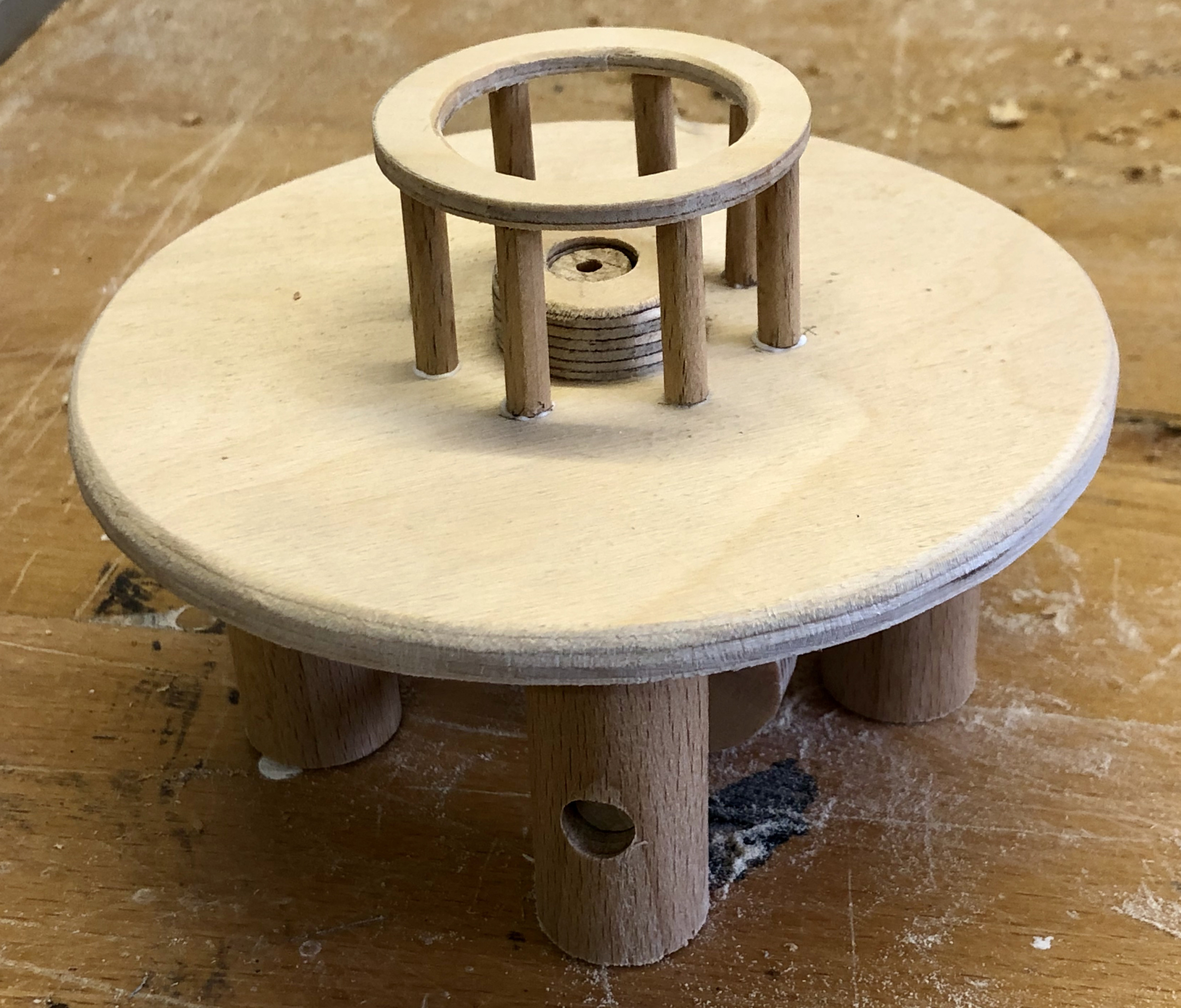
To push the petals up when the flower is closed, a wooden ring is required at just the right height. A certain amount of experimentation shows the correct height and some trimming of the outside of the petals gets them all to move synchronously.
A ring/cage at just the right height
Lessons learned
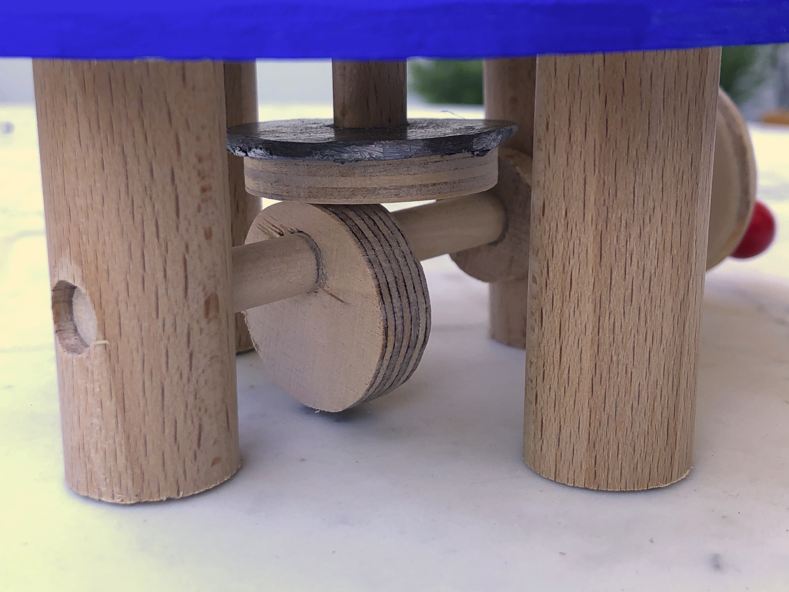
The flower jammed when open and didn’t want to close again. A lead washer fixed that.
Lead washer to increase downward force
It was caused by the vertical activating rod tilting due to the off-centre upward pressure from the cam. It’s a delicate balance between the diameter of the dowel and the diameter of the hole in which it moves. I used a 10 mm dowel in an 11 mm hole and that was too loose. Maybe a 10.5 mm hole would have been better, maybe I should have used a much slimmer dowel to reduce the surface area subject to friction? I will just have to try it and see in future.
What did the critics say?
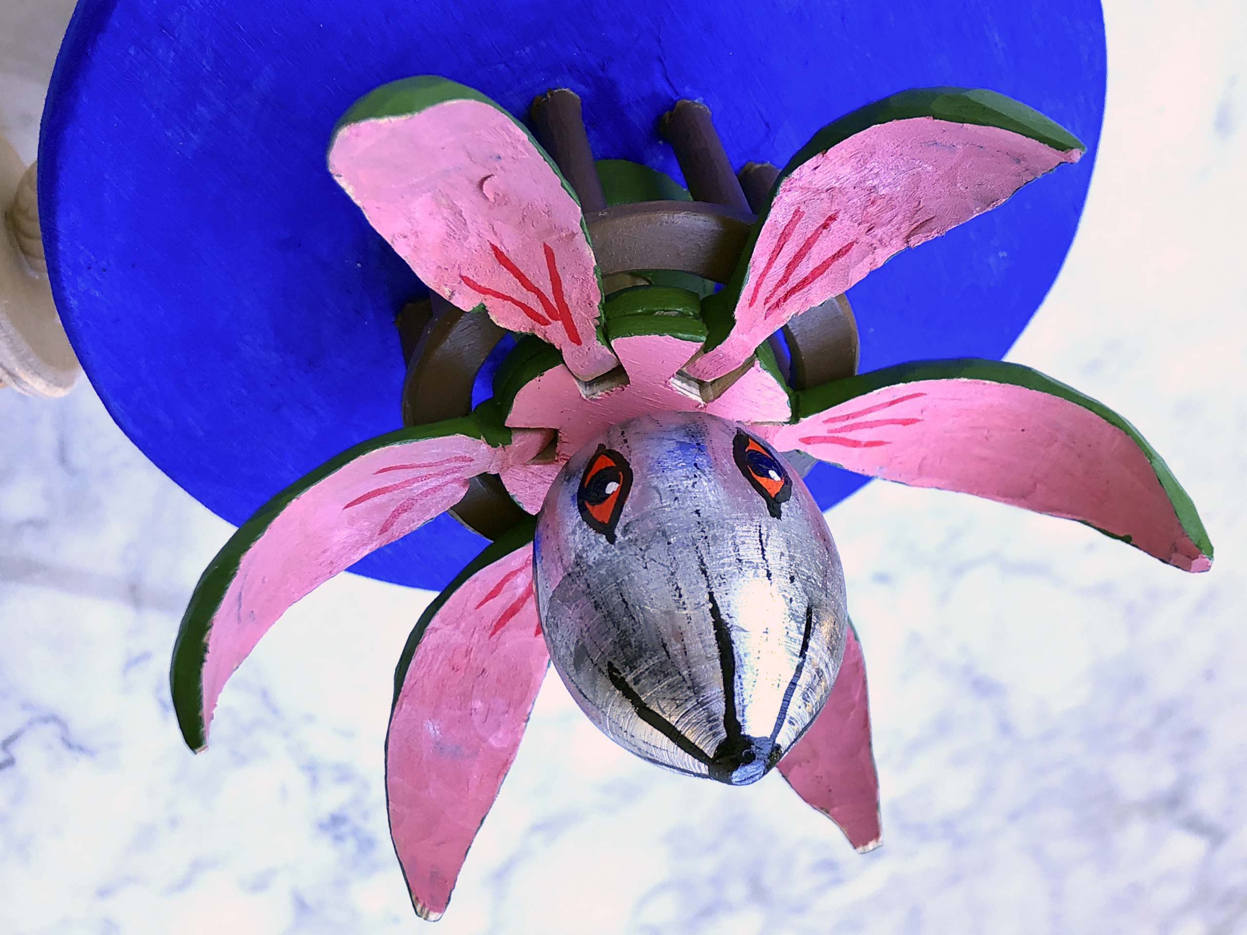
My severest 4 year old critic asked “are those rabbit’s ears?
Rabbit’s ears?
It only has 6 arms so it can’t be an octopus
Octopus?
Something from outer space?
Alien?
This finished piece has a very short narrative. Each turn of the crank opens & then closes the flower. That is not much of a story. Nevertheless my official tester played with it happily for quite a while. I think it is more something to entertain kids and is of less interest for adults. I had fun making it and learned a bit, so I am content.
The video
Video link “https://www.youtube.com/watch?v=uwzTALIhS_c”
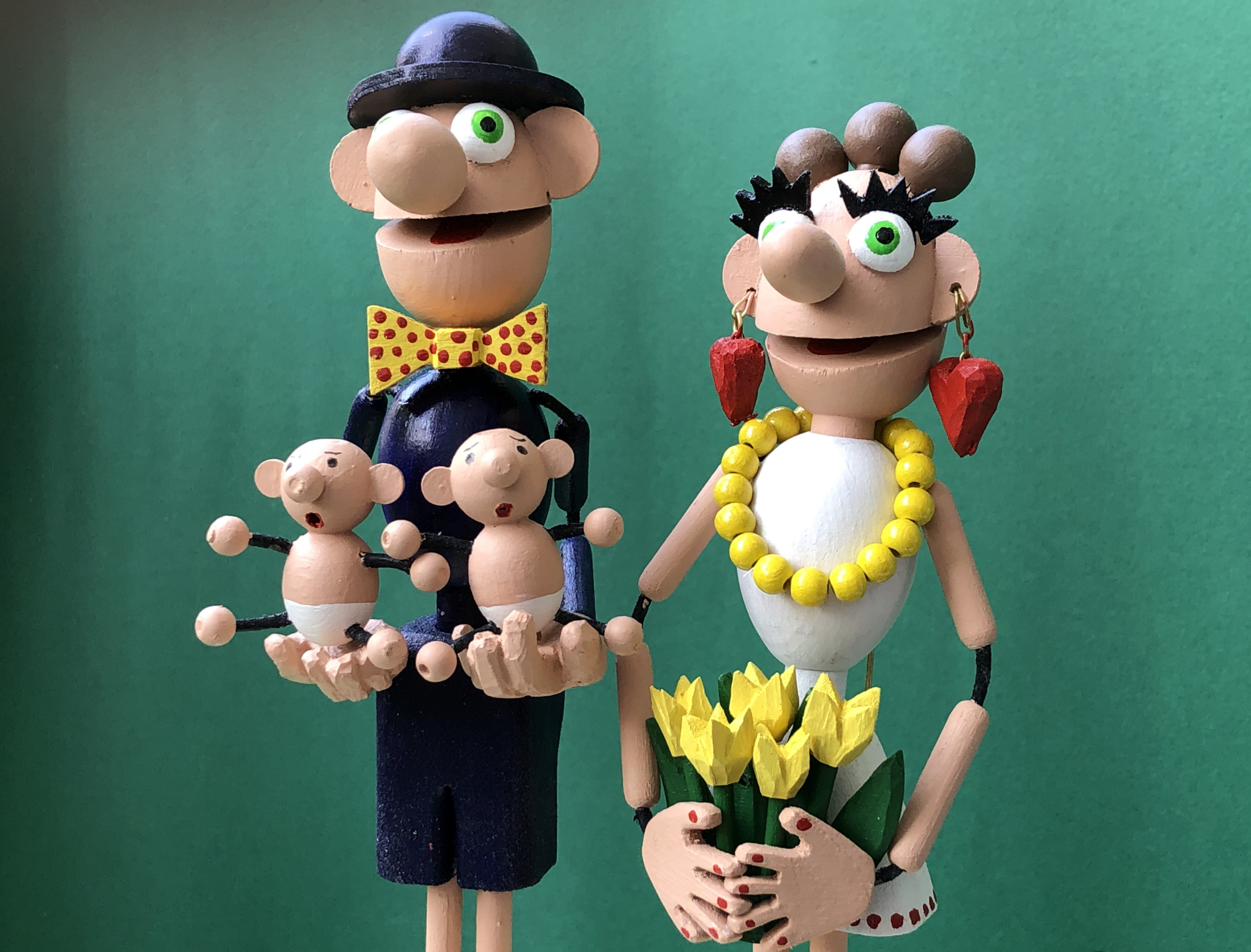
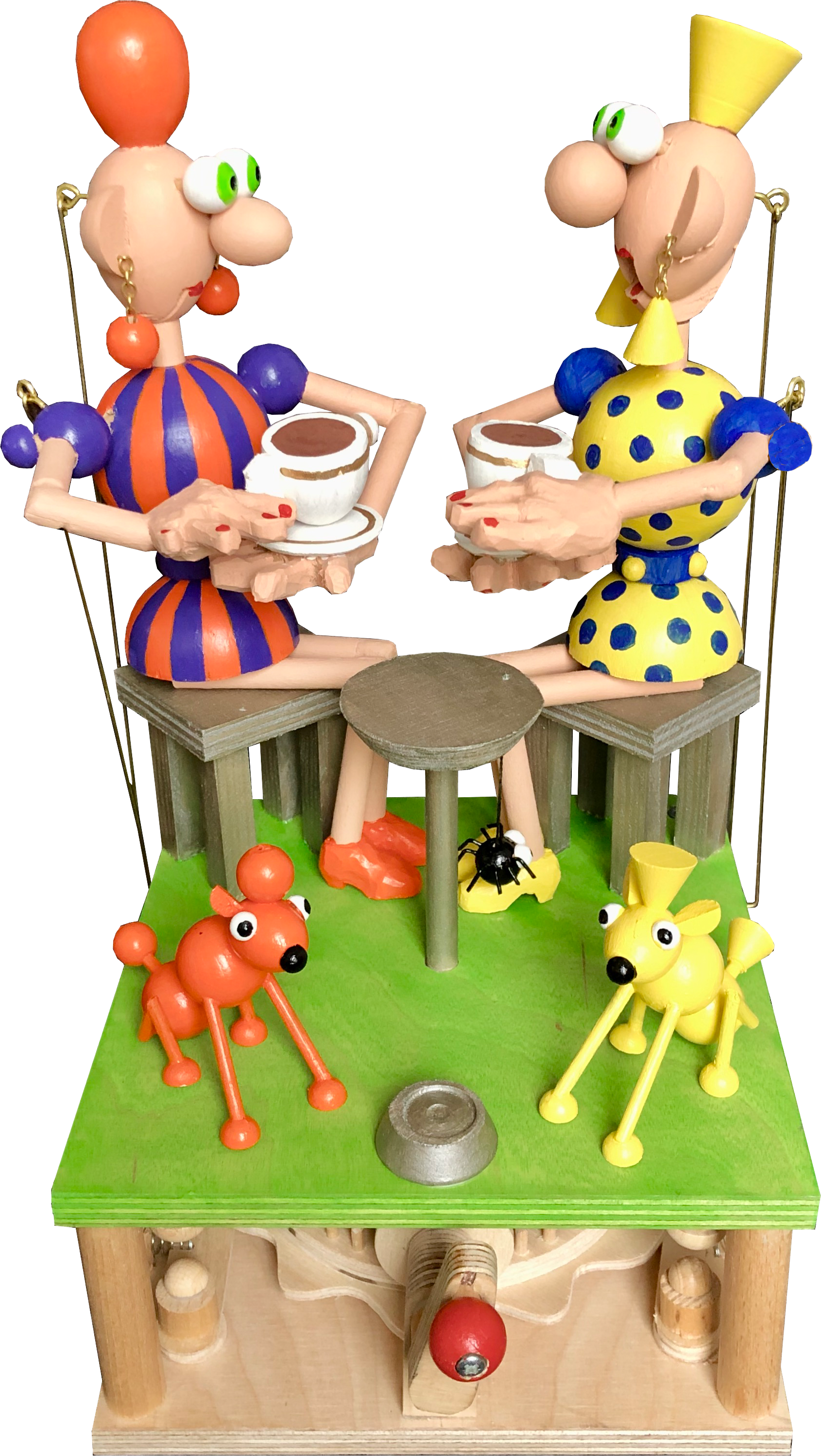
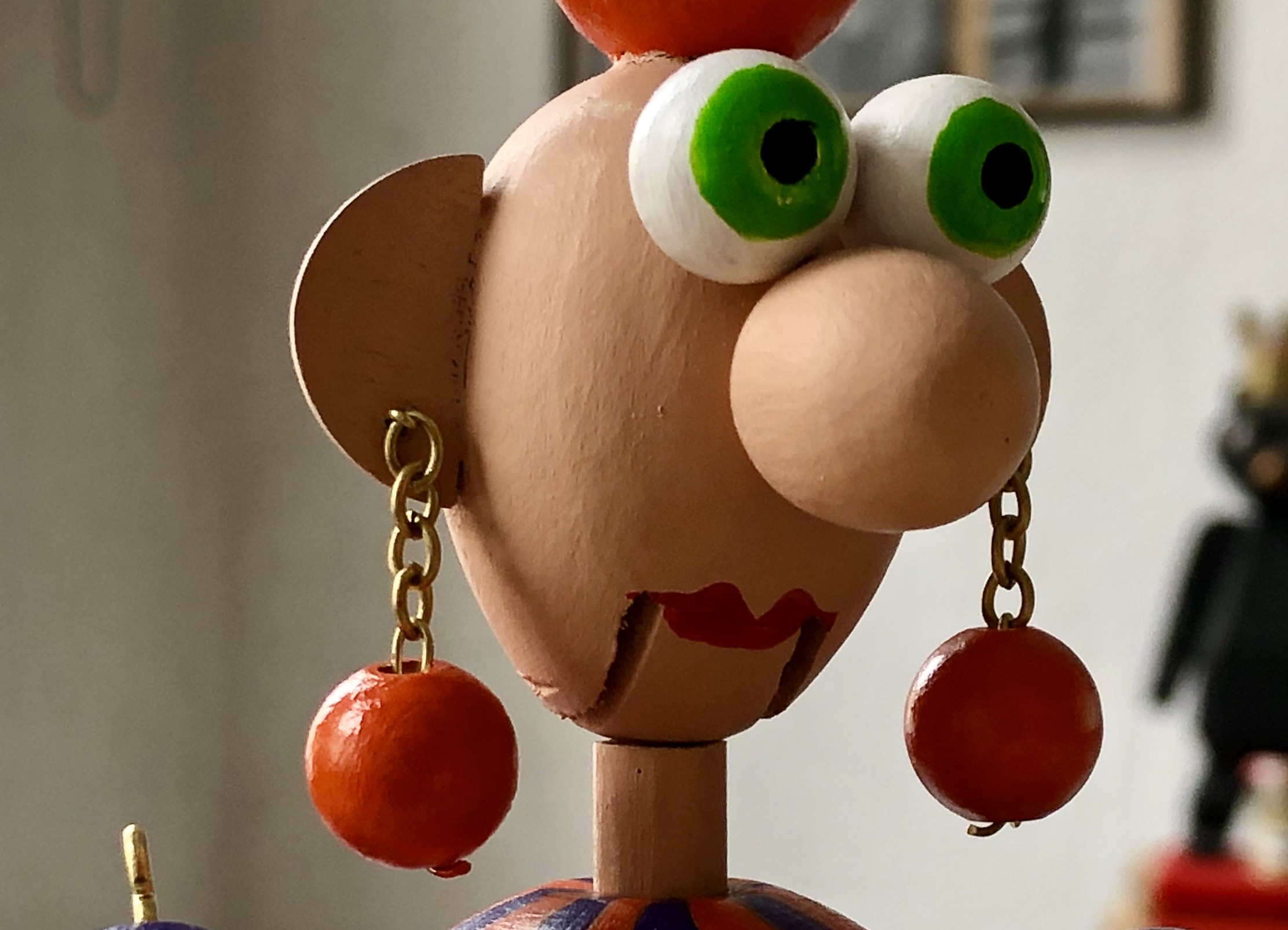
As an Englishman in Berlin I am naturally a staunch defender of English culture, so I aim to sell the benefits of teatime to the pagan Germans who much prefer coffee! When two chatty friends get together, the benefit of having to drink tea is that while one is drinking their delicious tea, the other can chat and vice versa. The more vivacious the chat the better, so waggling head & hair and dangling earrings are a must.
Dangly earrings are a must
What’s the technical brief?
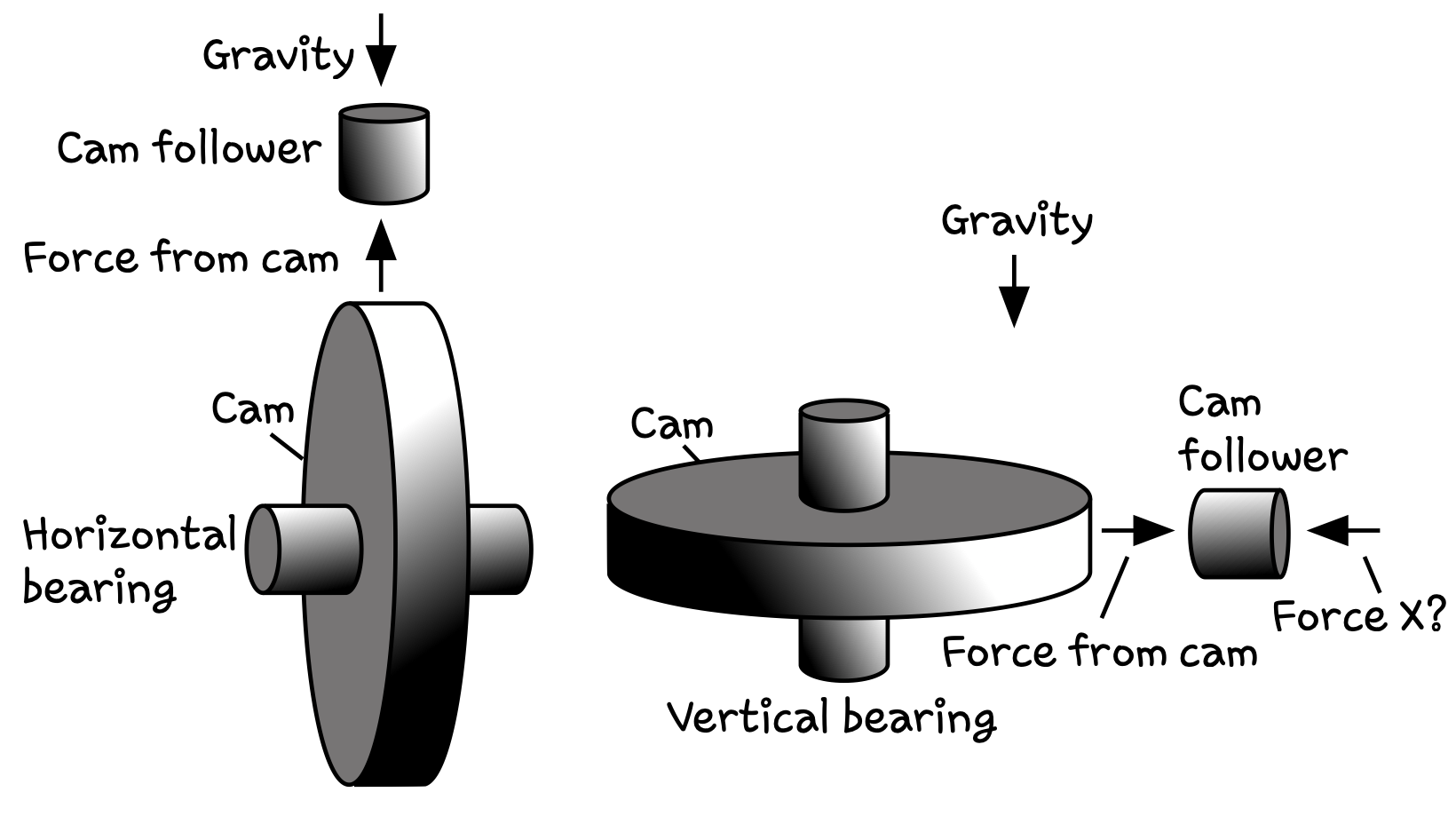
I like the idea of cams controlling things, but as I live in a small flat I see a drawback in the size of the base needed to accommodate cams which turn around a horizontal axis. I wondered whether arranging cams to turn around a vertical axis is feasible and whether the resulting base would be more compact.
This simple illustration shows the 2 options. At first sight the vertical bearing option looks distinctly flatter.
With a horizontal bearing, as the cam turns, the cam follower is pressed onto it by gravity. As the edge of the cam moves up or down, the follower moves with it, or follows it.
With a vertical bearing, gravity stubbornly remains a vertical force, so some other force X is needed to keep the follower in contact with the cam. It does however mean that several followers could share the same cam with a “phase” difference depending upon how far apart they are, angularly speaking.
Force X could be a spring, or we could use a piece of suitable routed string attached to a weight to pull the follower against the cam, thus bending gravity to the required angle. The angle of rotation of the handle should also be left to the user, so the cams should be “bidirectional”. The base should be as open as possible, so that you can see “the works”.
Additional ideas which came while making
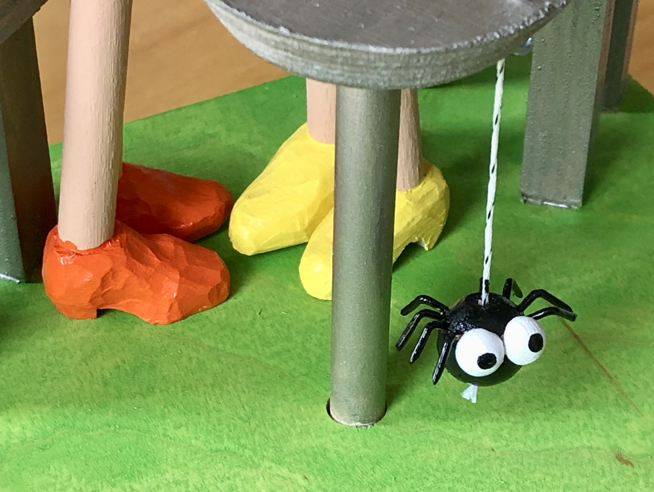
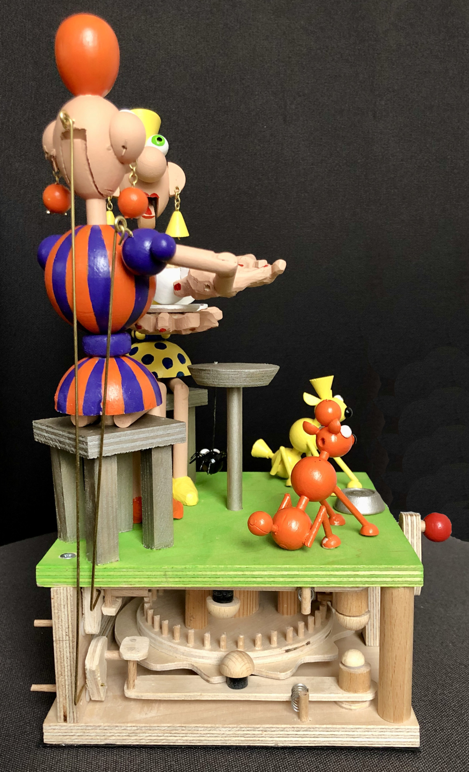
The bearing for the cams became the leg for a table.
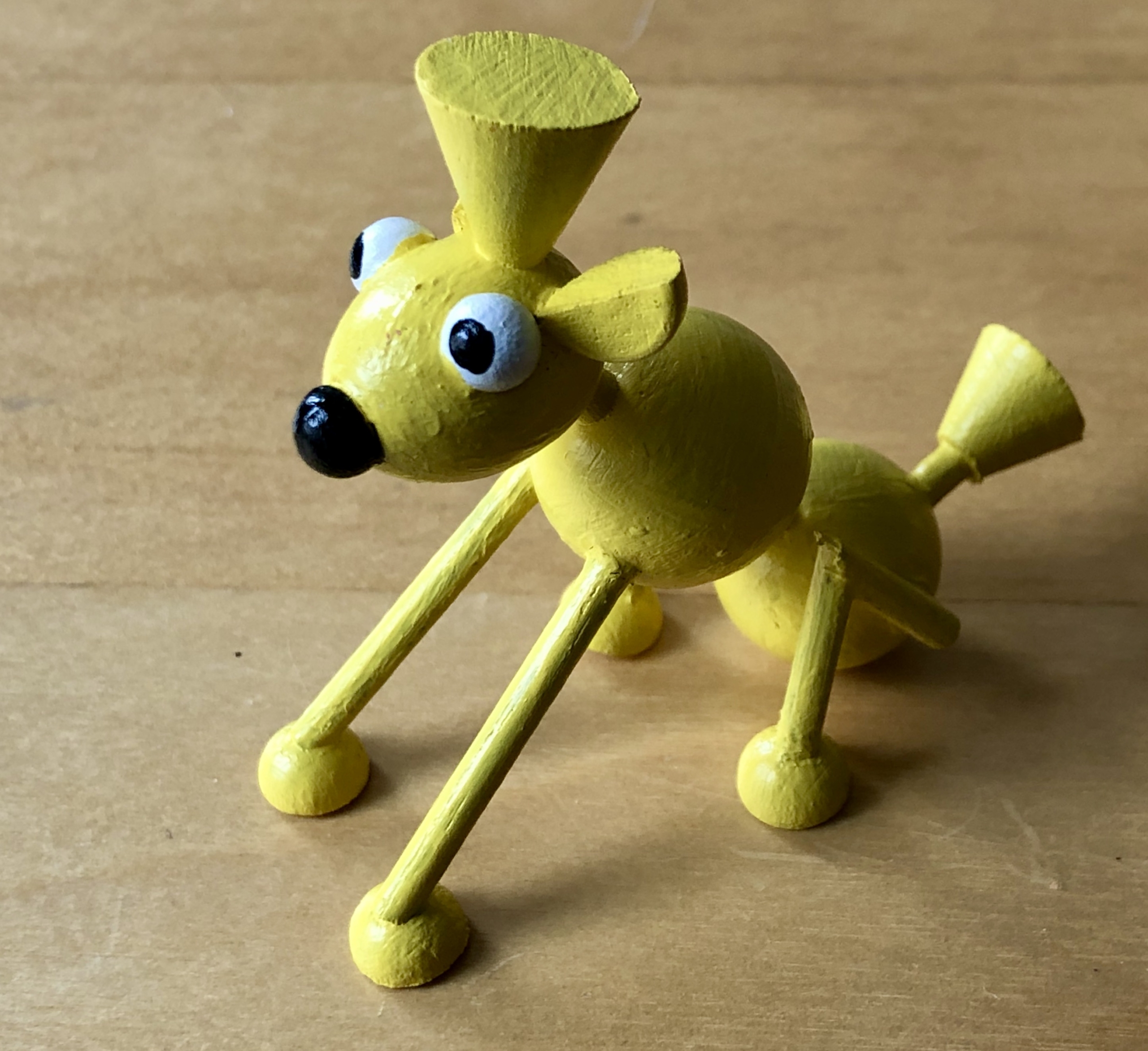
As the cam is in the centre of the base and the two figures are at the rear, the empty space at the front begged for something to fill it, so each of the friends has space for their dog which, as we know, always looks startlingly similar to its owner.
Small dog which is strikingly similar to its owner
The table rotating seemed to make no contribution to the narrative of the piece, so I almost stopped it from turning, but then I thought that it would make a splendid carousel for someone small enough to enjoy it, so that’s what it became, a tiny subplot within the bigger story.
A tiny subplot within the bigger story
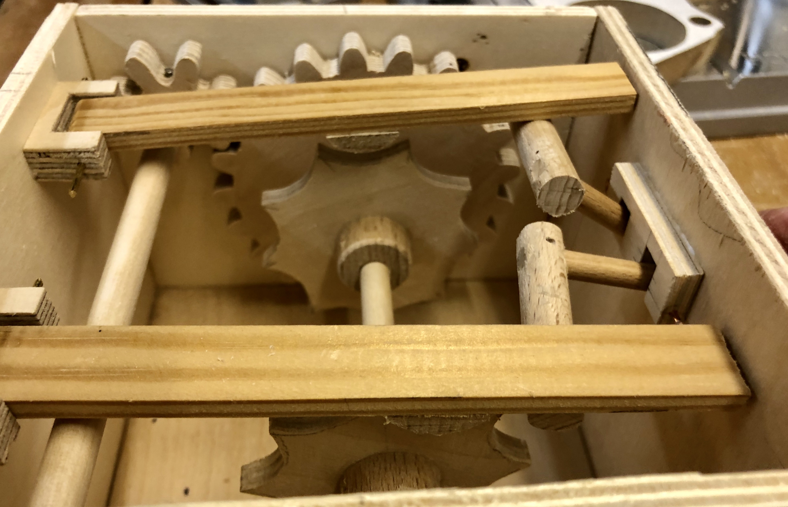
Gears
The cams will turn in the horizontal plane, around a vertical axis, but the crank for users to turn will rotate in a vertical plane, around a horizontal axis. Pin gears seem like a good idea, a small one with 8 pins for the crank and a large one with 36 pins to drive the cams.
The two pinwheel gears
The pinwheel gears engaging
For a smoother motion, (after I took this photo) I folded a piece of sandpaper into a V-shape and chamfered the tops of two of the pins at a time in the large wheel. This is not needed for the small wheel.
Cams
Each figure has two moving parts – the mouth and the arm which lifts the tea cup. As good friends they take turns to speak and while they are not speaking, that’s the opportunity to have a slurp of tea. I decided to just use two cams. Each figure is driven by the same two cams but with a 180 degree offset. While one figure is chatting the other one is slurping and vice versa.
Two cams
In the above picture the left sort of egg-shaped cam is responsible for lifting the arms, the right cam for opening the mouths. When not chatting (the wavy bit) the mouth is held open to await a slurp of tea. Note that there are no abrupt steps in the shape of the cams here to make sure that it will work in both directions.
Followers
There are 4 followers mounted on levers which are pivoted at the front of the base, two for the lower cam and two for the upper cam. In the photo you can see the pivot at the left, the follower in the middle with a plastic ring to cut down friction, and at the right the part which drives the mechanism mounted on the rear wall.
Two follower levers
In this photo of the base you can see two followers with small springs to keep them in contact with the cams.
Base with two follower levers & springs
The rear wall mechanism
Changing the direction of motion
As the lever to which the follower is attached moves, it in turn moves this small mechanism, which has the effect of changing a horizontal motion into a vertical one. As the lever moves out it turns the triangularish piece of wood around its axis at the bottom. The row of small holes in the side are to take the vertical brass rod which moves the model. Unsure as to how much movement was needed, I could thus choose a hole and shorten or lengthen the movement by trial and error. This mechanism is repeated four times for four followers.
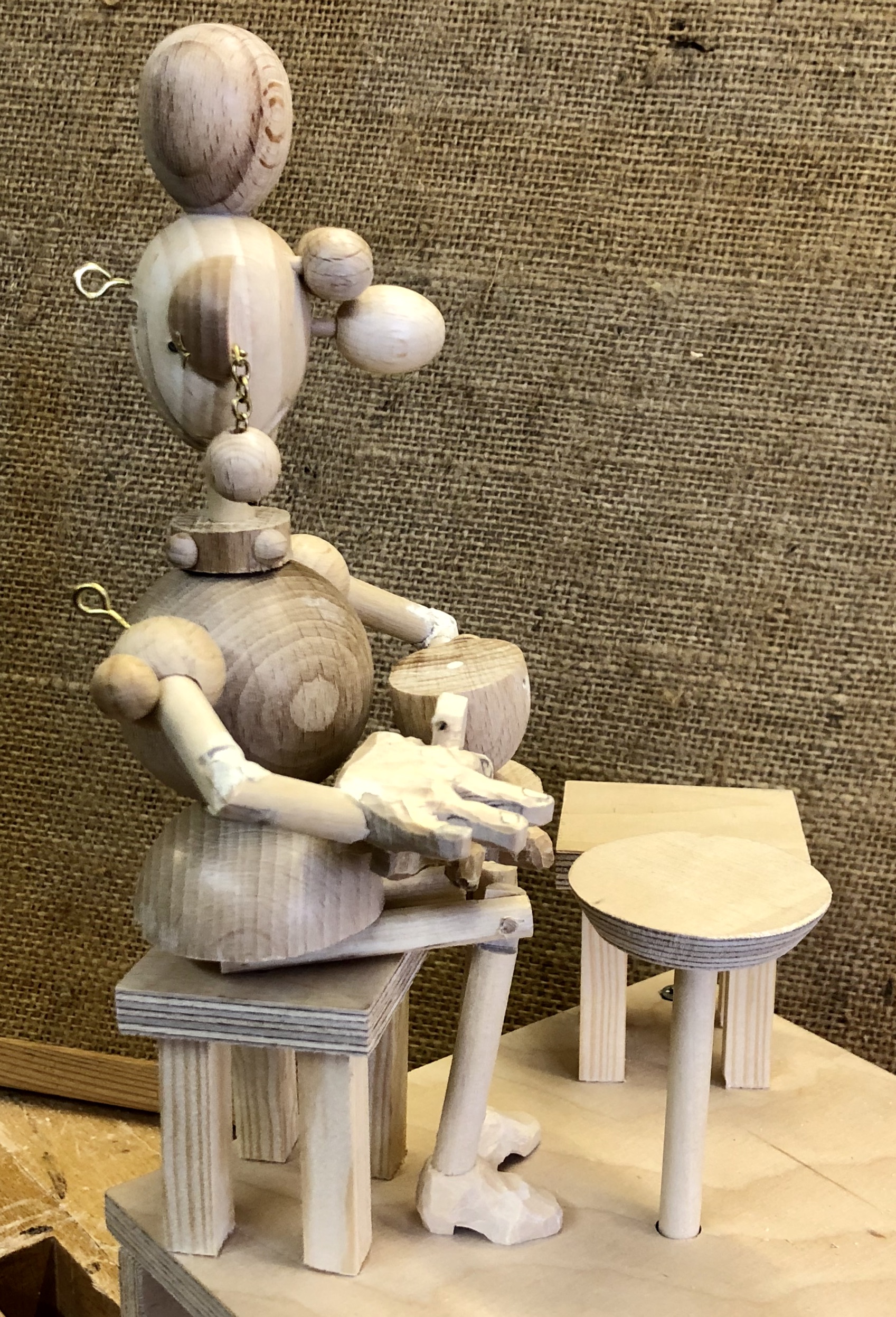
The tea drinkers
Half of a 40 mm wooden ball serves nicely as hips.
The figures are assembled along a piece of 8 mm dowel which is fixed into the seat. This means that they are adjustable. I left the knee hinged on a piece of 3 mm dowel until I was happy with the pose, only then gluing it. Half of a 40 mm wooden ball serves nicely as hips.
A whole wooden ball makes a good torso
One of the arms is hinged on the body to lift the cup of tea. The other arm is fixed to carefully hold the saucer.
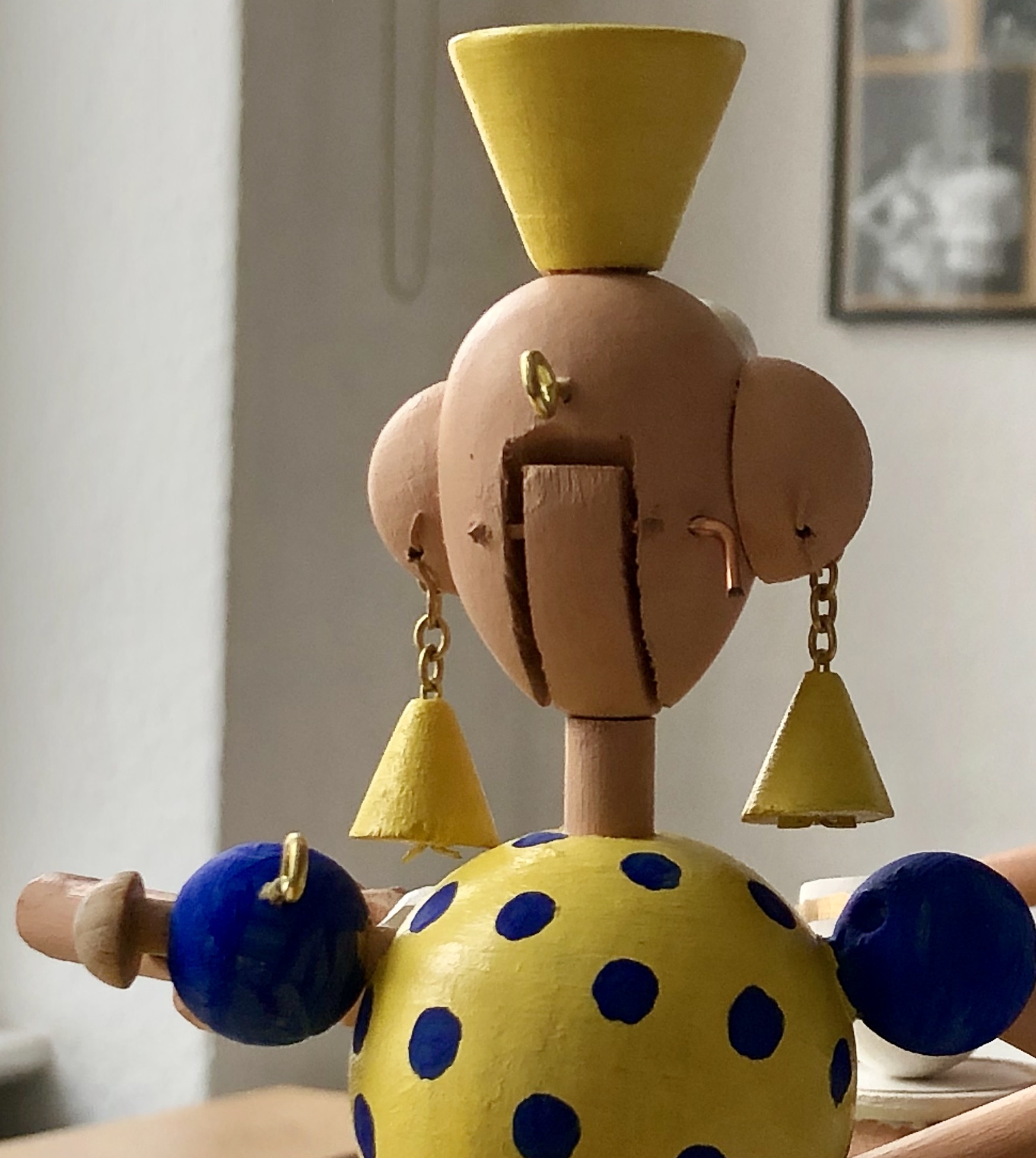
A few wooden eggs & balls serve as the head and hairdo
The jaw is fixed to the 8 mm dowel and the head is then hinged onto the jaw. This means that the whole head moves when the figure is speaking/drinking tea, causing the earrings to swing about most satisfactorily. The eyes and nose are removeable to make painting easier before gluing them in place.
The head is hinged onto the fixed jaw for maximum waggle
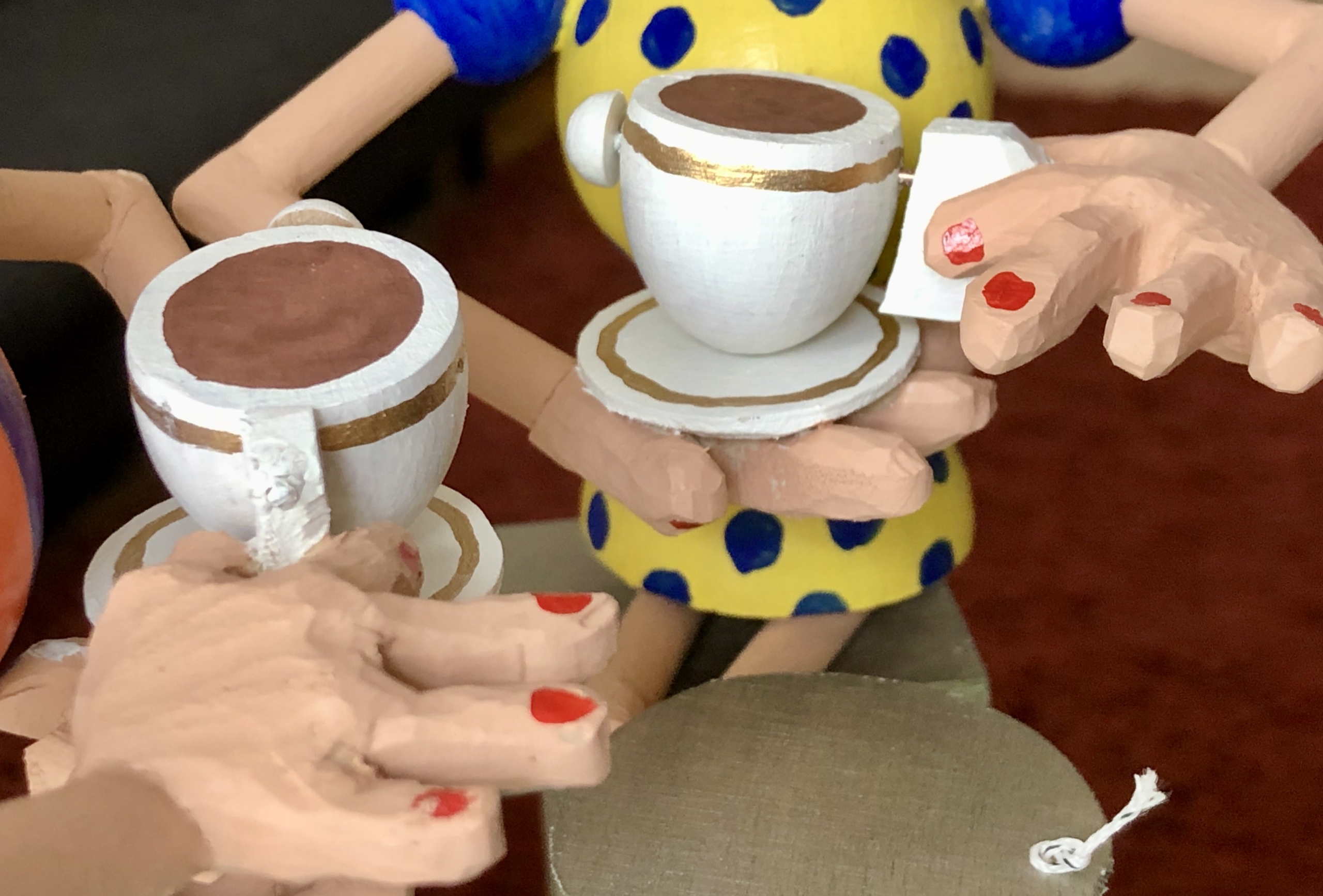
Hands and teacup
Carefully hinged woodwedge teacups
The hands are carved from lime wood with the smallest finger slightly lifted. When the arm lifts, the protruding pinkie then makes that elegant gesture so typical of polished tea drinkers. Of course the teacup must stay horizontal to make sure that nothing gets spilled so it is hinged on a bit of brass rod.
The brass rods in place
Lessons learned
I ended up with quite a compact base so it was worthwhile turning the cams sideways. Precision seems to be more important like this however, so I had to take great pains to keep the two cams parallel to one another as well as to the box. The spacing between the two pin wheels also had to be just right for smooth operation. Fortunately, I could adjust that a bit via the thickness of the washer underneath the cam assembly. When I was almost done, I decided to use what I had intended to be a collar as a waist instead. Happily, that just meant changing the order of the bits on the 8 mm dowel. The figures look much more stylish like that. When testing the movement, I decided that the mouth was chattering too quickly, so I made a new cam from 3 mm plywood to slow things down a bit. I tried to resist gluing parts together for as long as possible to keep my options open. That is a delicate balancing act. While things are not fixed the precision wobbles and occasionally pieces tumble all over the place and have to be carefully collected. Once glued it can be hard to take things to pieces again to change this and that.
Youtube link https://www.youtube.com/watch?v=COTnQGcVq34
Fitness is a big deal in Berlin with fitness centres popping up everywhere like mushrooms. However, you don’t have to become a member of one of these joints to stay fit as Yolanda the Yoga Queen can show us.
Yolanda is a moving example of the ancient art of wooden Yoga. Yolanda’s wooden Yoga skills are so advanced that she has mastered the technically very demanding eyebrow twitch, even accomplishing the plait swing with simultaneous neck stretch first recorded aeons ago in the darkest depths of the forests surrounding Berlin.
As a master of her craft, she is entitled to wear the Navy blue initiate’s frock, with its matching conical headpiece.
Inspiration
A friend gave me an A4 card with a figure to be cut out called “Gymnastics with Sister Adelheid”. You can see it halfway down the page http://www.edition8x8.info/bastelbogen/bastelbogen.html I had a lot of fun making this and when you lift Adelheid’s substantial body up and down, her arms wave down and up in a most fetching manner!
Adelheid was created by Martin Graf who is a brilliant artist with a great sense of humour. His web site is in German, but the images and animated GIFs speak for themselves, so it’s a great source of inspiration.
So what’s the brief?
The nurse who looked after me as a 10 year old was called Yolanda and I loved her dearly. She also rhymes nicely with Yoga, so that was that. I also decided to change the movement so that when Yolanda’s body is pressed down, her arms go up. Trendy girls in Berlin favour long hair at the moment, so I thought that long plaits would be nice for her and maybe they could move up and down too. While considering how to do this I thought well let’s move her eyebrows as well.
The body, arms & legs
I used three sheets of 6 mm plywood sandwiched together for the body in an almost triangular shape. For the arms I used 2 mm plywood with carved limewood hands and shoes. The legs are 6 mm beech dowel with 1.6 mm metal rod to move the arms. In the middle piece of the 3-layer sandwich there are slots in the plywood to accommodate the legs and the springs which push them down. This middle piece has an angled top on which the arms rest. Three small polyamide washers help the arms to move freely and I cut grooves in the outer pieces of the sandwich to provide space for the bent metal rods to move up and down.
To move the arms
This arrangement means that when you push down on the body, the leg springs compress and the metal rods move up into the body thus lifting the arms. As each leg has its own spring, you can choose to place one foot onto a raised platform leaving the other foot floating free in the air. If you then push down on the body only one arm will be lifted. As the ruff is fixed to the body, you can also push down on the ruff.
The head
I cut a beechwood egg into two halves as the basis for Yolanda’s head, I chose a smaller egg for her nose, two hemispheres for her eyes and a cone for her hat. I used 2 mm plywood for her plaits and carved a limewood ruff to hold her 6 mm dowel neck.
From left to right. Front of head with holes for eye axes. back of head, 2 pieces of padding and 2 plaits. 2 eyes at bottom on different length rods.
To understand how things move, here is a partial assembly, showing just one plait which is pivoted on the metal rod on which Yolanda’s right eye (and eyebrow) is fixed on the outside.
As the metal rod from the neck moves up and down it moves the plait up and down. The plait is fixed with epoxy resin adhesive to its axis rod, so this rod turns as the plait is moved. The eye on the outside is also fixed to the axis rod, so it also turns as the plait is moved. Here’s a short video showing the movements https://www.youtube.com/watch?v=pejNGatJAyQ
The plaits overlap so I added padding on each half of the egg to keep the plaits properly offset and to fill what would otherwise be an ugly gap. This padding means that one eye needs a metal axis rod which is longer by the thickness of the padding. A plastic washer beneath each plait keeps it moving freely.
To move the plaits & eyebrows
The ruff is glued to the top of the body and the neck is glued to the ruff. The neck can move within the head thus moving the brass rod up and down. I chose not to use a spring here so that friction can hold the head on the neck in any position that you choose. To lift Yolanda’s plaits you have to pull her head upwards, “stretching” her neck. To lower the plaits you press her head down. Her hat is a good place to hold because your fingers are then clear of her eyebrows. As each plait lift its metal rod turns, rotating Yolanda’s eyes.
Her eyebrows are glued to the tops of her eyes and move with them. As her plaits lift her eyebrows tilt and Yolanda seems to frown. As her plaits go down, her eyebrows relax and Yolanda appears calmer. You don’t really notice that her eyes are rotating, her eyebrows grab your attention and give her this variable expression. Once you have set her expression you can then use the ruff to press the body down and lift her arms, without changing her expression. If you choose, you can press down using her hat, in which case her expression will first relax and then she will lift her arms.
As a well brought up young lady Yolanda takes care to use white cotton ribbons to keep her plaits tidy, which of course match her snow white ruff and socks.
Sometimes Yolanda gets a bit cross. Well it’s only human isn’t it?
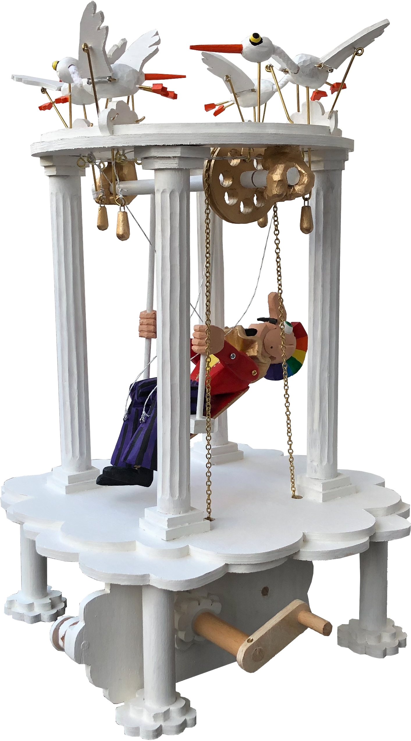
What does it take to make us happy? How do we get to seventh heaven or even up onto cloud nine?
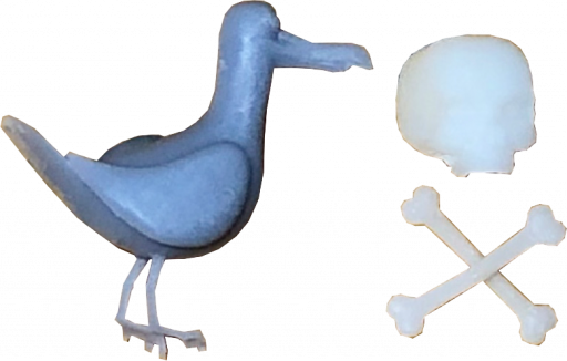
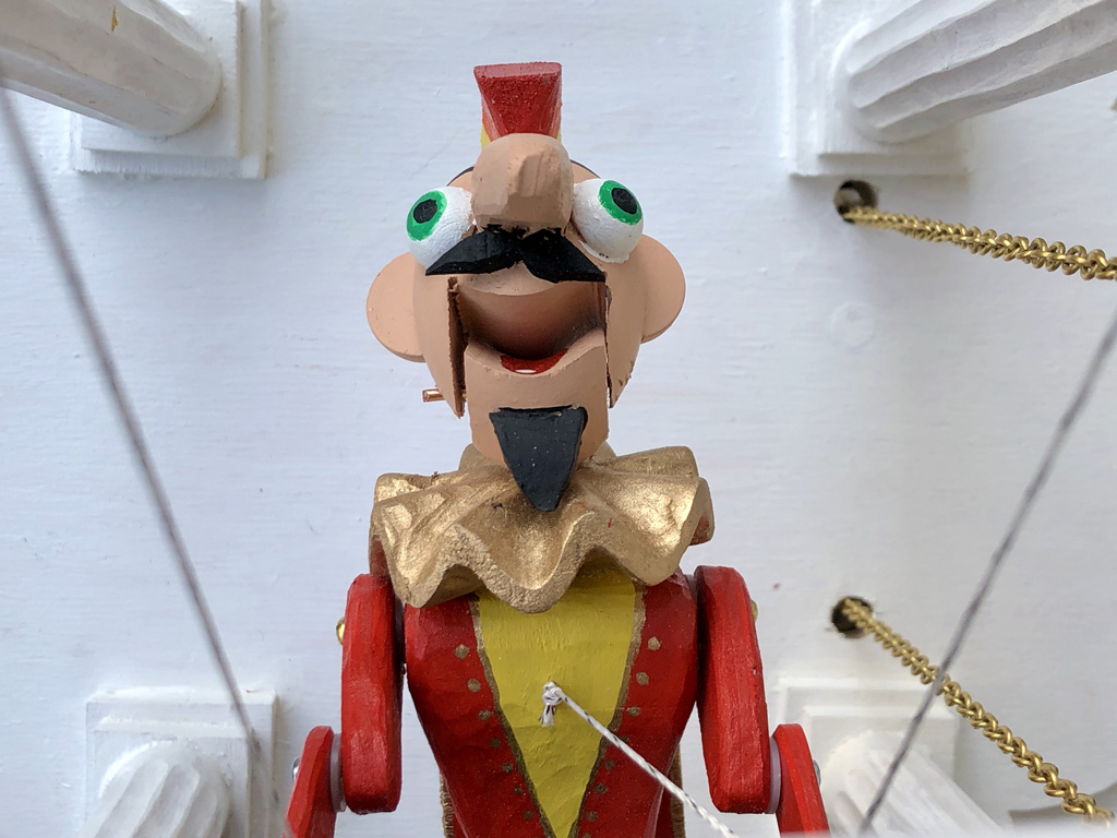
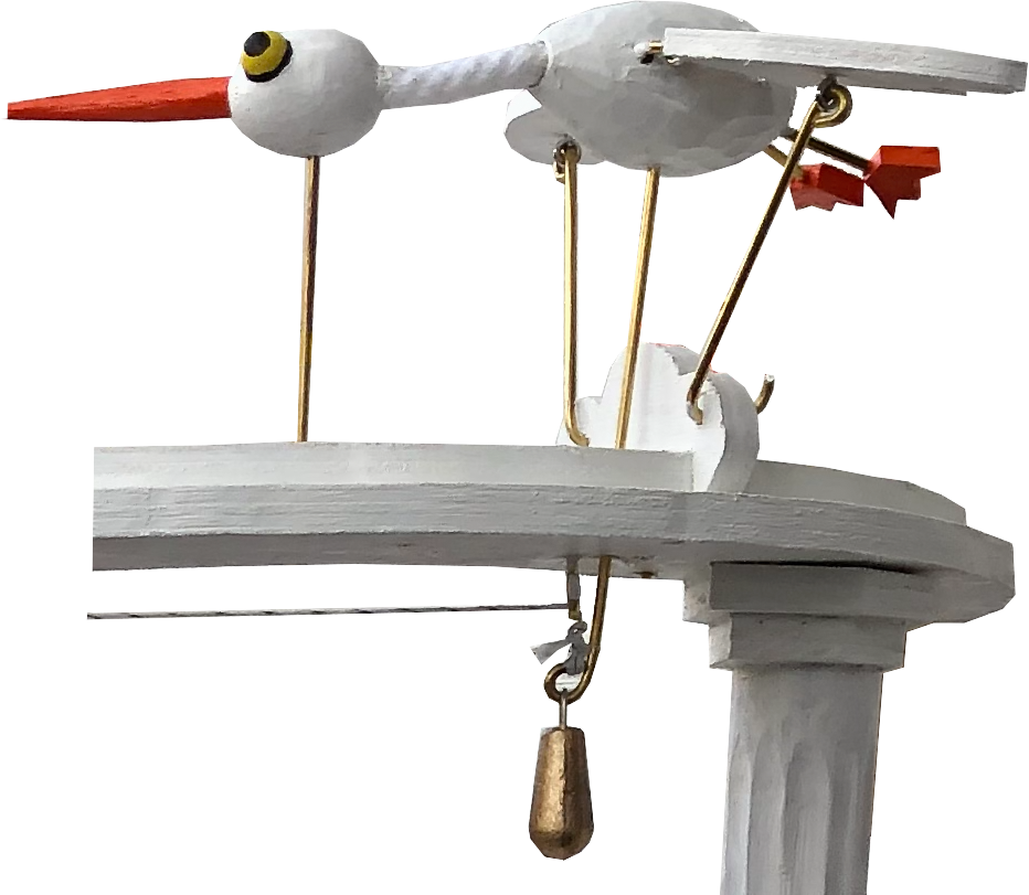
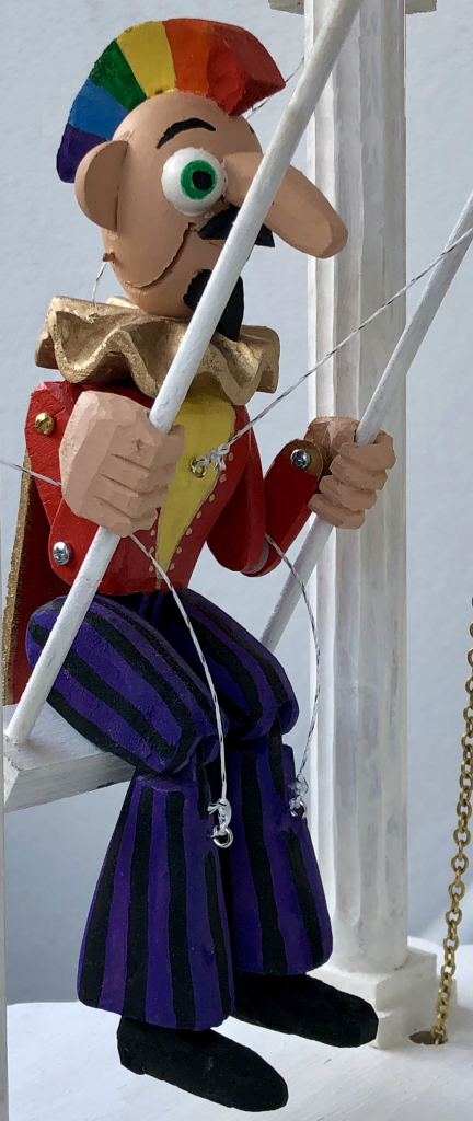
It’s really the small things in life which count and seeing my wife enjoying a swing in the garden outside a mountain restaurant in the Alps I thought that would be a great start. Originally, I planned to put the swing in a bird cage but then I thought “who’s happy being caged in?” So I decided to swing on a star, carry moonbeams home in a jar, trala and use clouds to swing on instead. There was recently an exhibition in Berlin about hippies and psychedelia, so I decided that a strange bird will sit on my swing, with a psychedelic Mohican haircut, a strange bird who really knows how to enjoy life. To keep him company, I added some heavenly birds who might even be storks just back from delivering their latest load of babies.
Pure happiness
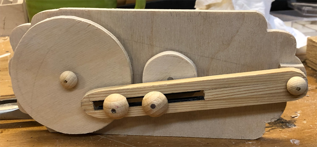
The basic mechanism
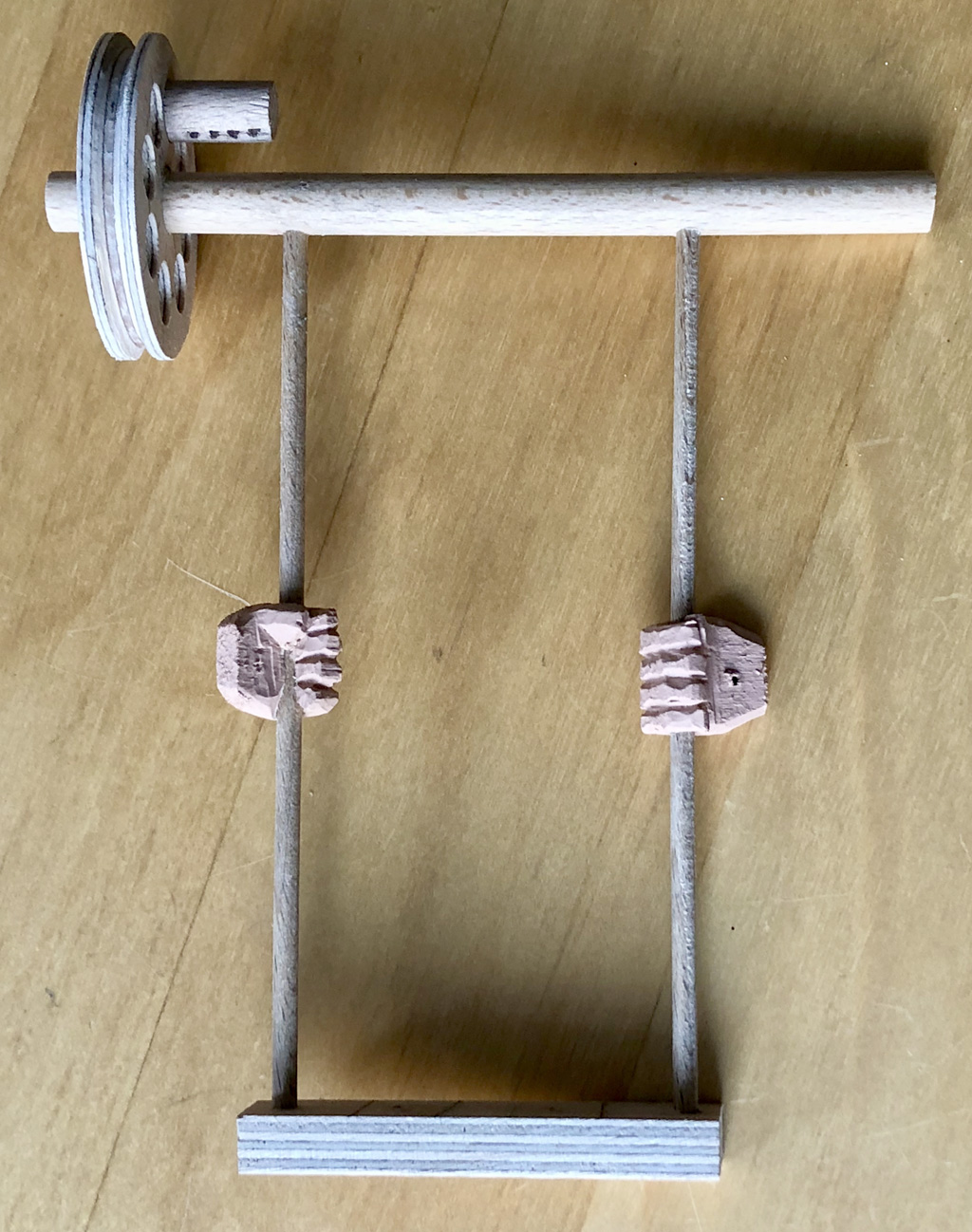
I decided to use a crank to turn a small wheel, which then causes a larger wheel to first turn one way and then back the other way.
The basic mechanism. The small central wheel is turned by the crank on the outside of the partition. This causes the big wheel at the left to rock back and forth. Note the black plastic strips in the slot to reduce the friction. These are cut down tie-wraps.
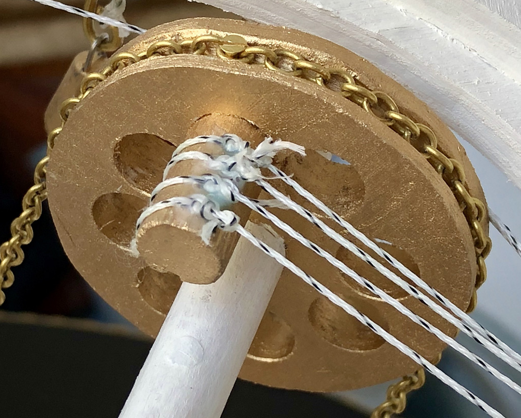
For an extravagant visual impression, I chose a golden (brass) chain to provide the drive to the top axle. This is screwed to the big wheel beneath the base to transmit the motion to the top of the swing, where it is also screwed in place.
The wheel to make the swing rock back & forth and to pull the strings which operate the birds.
The same wheel at the top which makes the swing rock also pulls the four strings to make the four birds rise up. Strategically placed screw eyes guide the four strings to the four birds.
A string threaded through an eyelet pulls the brass rod up which lifts the bird’s body, the lead weight pulls it down again.
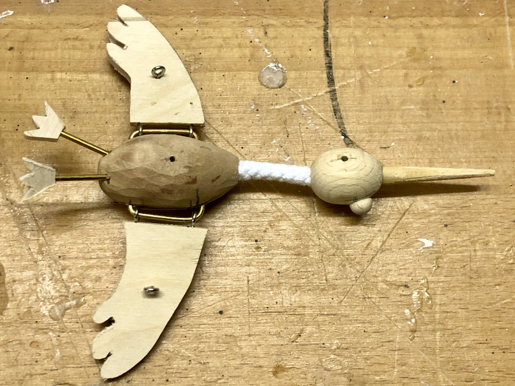
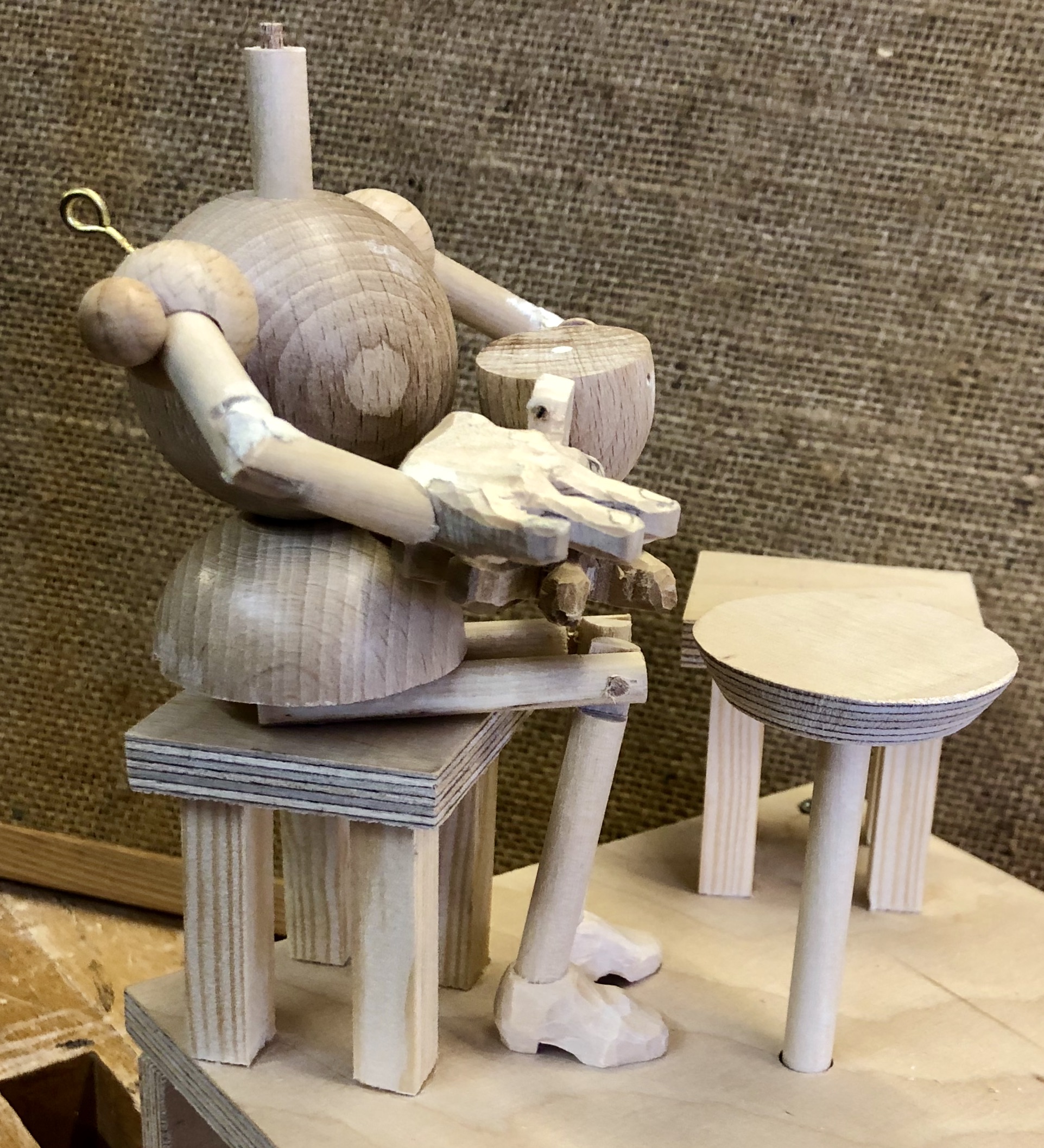
The swinging man
The swinging man has to really enjoy his swing as he is in 7th heaven, so moving forwards he leans back and pulls his legs up with his mouth open laughing. Right at the back, ready for his next swing, he sits up straight with his mouth closed and his legs hanging down.
Like a puppet, he has strings on his legs and a string on his chest. These strings are permanently tied to the framework. As the swing moves forward the strings tighten to pull his legs up, As the swing moves back the string tightens to pull his upper body erect on the seat. Gravity closes and opens his mouth.
His hands are permanently glued to the rods and his thighs are glued to the seat so that his body and lower legs can move freely.
The separate parts of the head and the carved ruff for our fashion-conscious swinger
The head assembled onto the body. Cutting a curved smile into a beechwood egg requires the egg to be held very firmly in a clamp.
One limewood leg, hinged at the knee on a 3 mm dowel.
The arms hinged with screws and plastic washers and the hands which hold the rods of the swing.
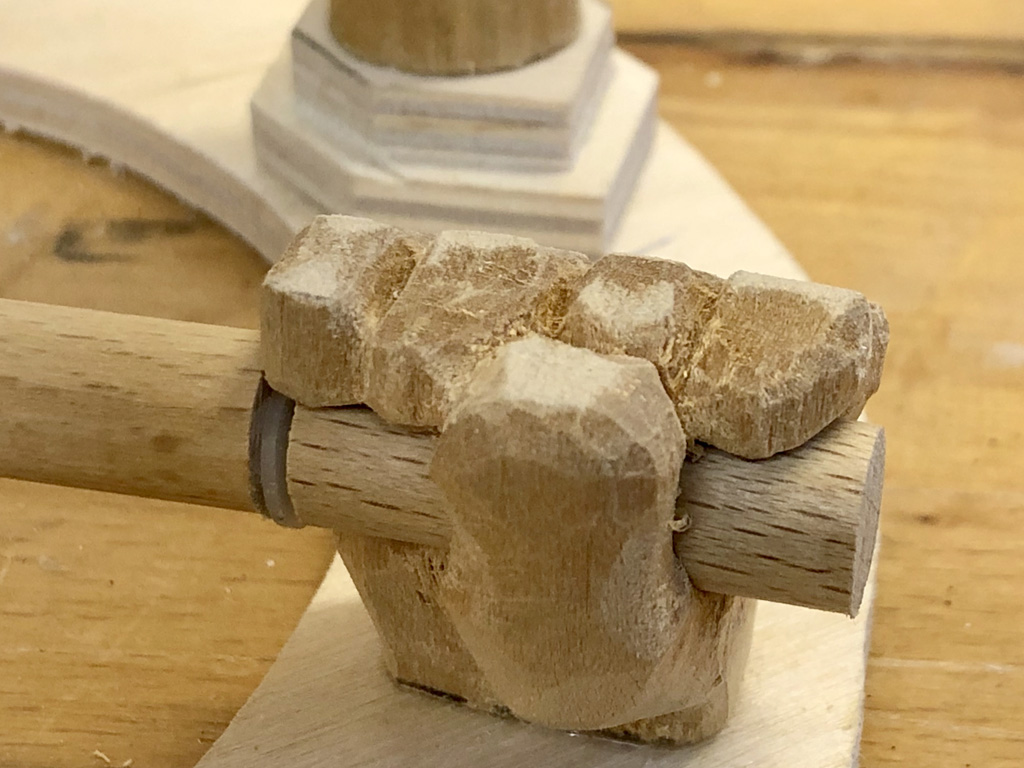
The wings are hinged to the body using screw eyelets and a piece of bent brass rod. The neck is a piece of white cord which flexes nicely as the body moves relative to the head. My harshest critic, a four year old neighbour asked me why the birds don’t move around in a circle although they are flapping their wings. She is quite right of course and a slightly more complex mechanism would have made that possible. I will tie a knot in my hankie to have a go at revolving birds at some future time.
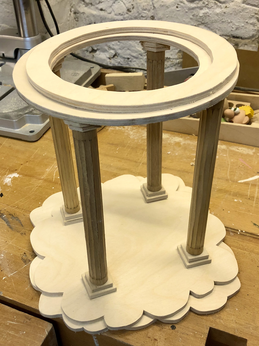
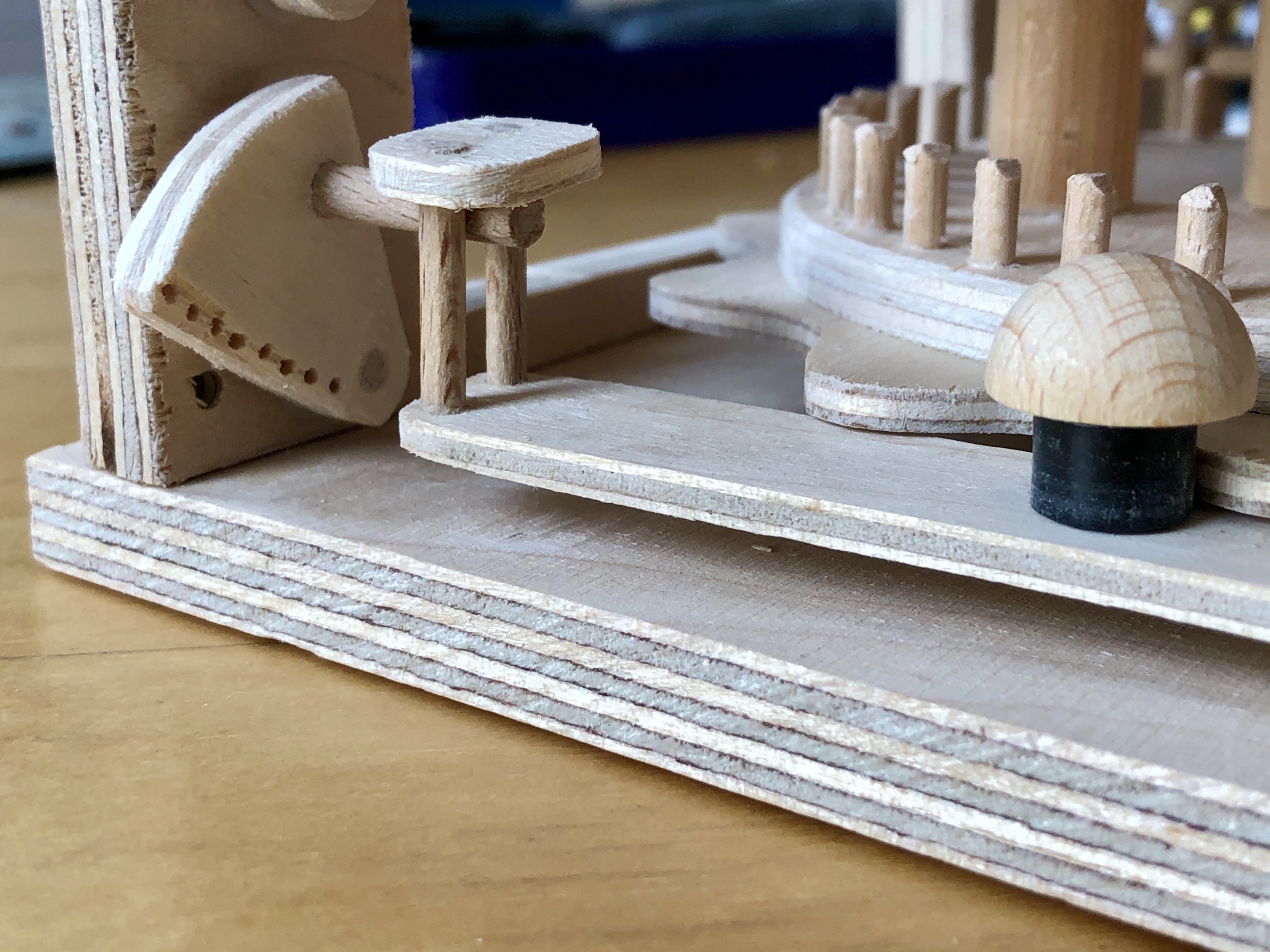
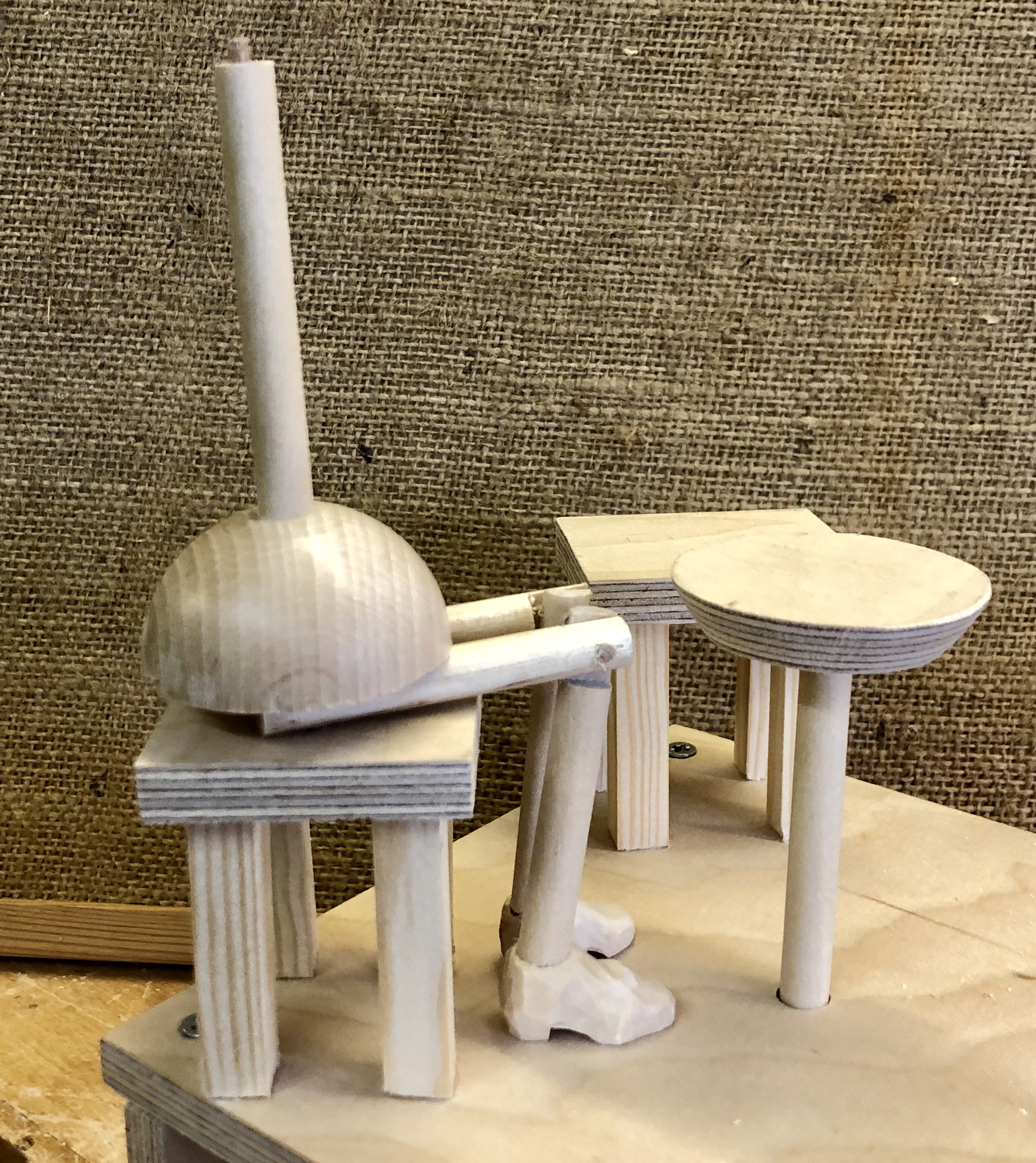
The heavenly supporting frame
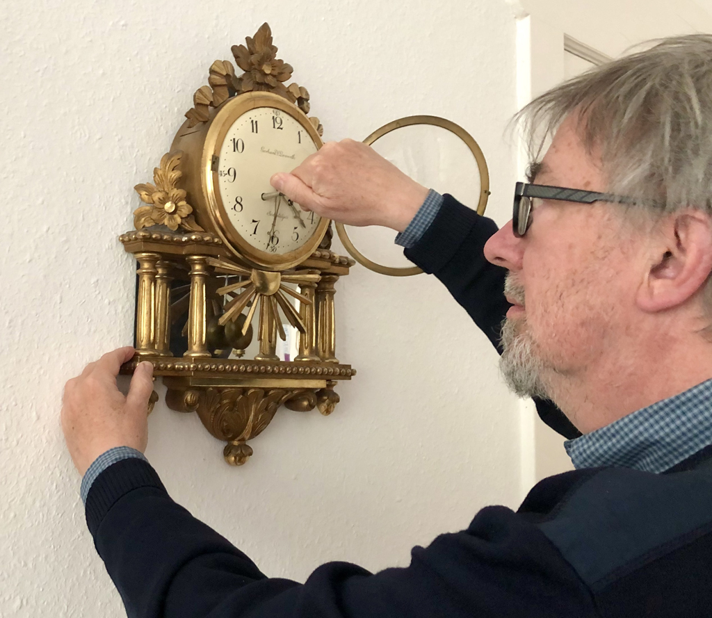
The framework is reminiscent of a Roman temple. The fluted columns are pieces of dowel with round chiselled grooves.
Everything is of course floating on clouds and I chose columns as in an ancient Roman temple to support an ethereally round top. Giant golden hands firmly grasp the ends of the axle for the swing. It is all made of wood, but a lick of gold paint gives things that certain sheen which we would expect in our Seventh Heaven.
The driving wheel was cut with a bowsaw and the groove in its edge was simply chiselled out. Drilling round cutouts supports the impression of a metal wheel when the gold paint is added. The hands could move at first, until trial and error revealed the best position for them to be glued.
The hands were first modelled in plastercine. The hole for the dowel was drilled first and only then was the final shape carved.
Lessons learned
It was fun making this but, as always, I was much wiser at the end than I was at the beginning. Initially I was very casual about the dimensioning of the moving parts and had to beef things up a lot when I noticed my mistake. After some strengthening, the mechanism works, although turning the crank requires a very uneven amount of force depending upon its angle of rotation. The finished item is quite large and the birds are easier to see than the “main” figure on the swing. Of course the columns and round roof are required to support the top axle but they do obscure our psychedelic hero enjoying one of life’s simple pleasures, which is a pity. Maybe a simpler inverted V-shape frame would have been better, without our feathered friends fluttering away up above. I still like it anyway!
“La Voyage à Nantes” is a regular summer event designed to promote the currently not very well known city of Nantes, which in 2019 took place from 6th July to 1st Sept. It is very simply organised around a long green line painted on the floor which leads visitors through the streets, passing both temporary and permanent artworks, including the amazing giant elephant which David Soulsby described in the January 2019 edition of the magazine.
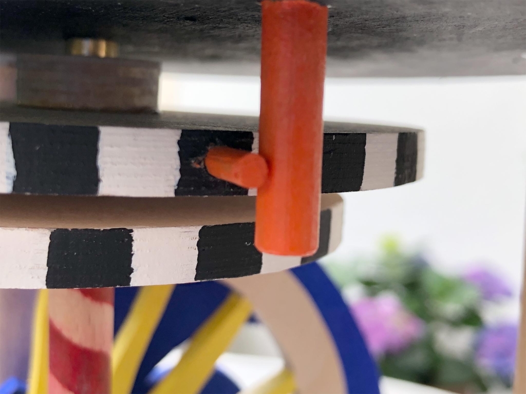
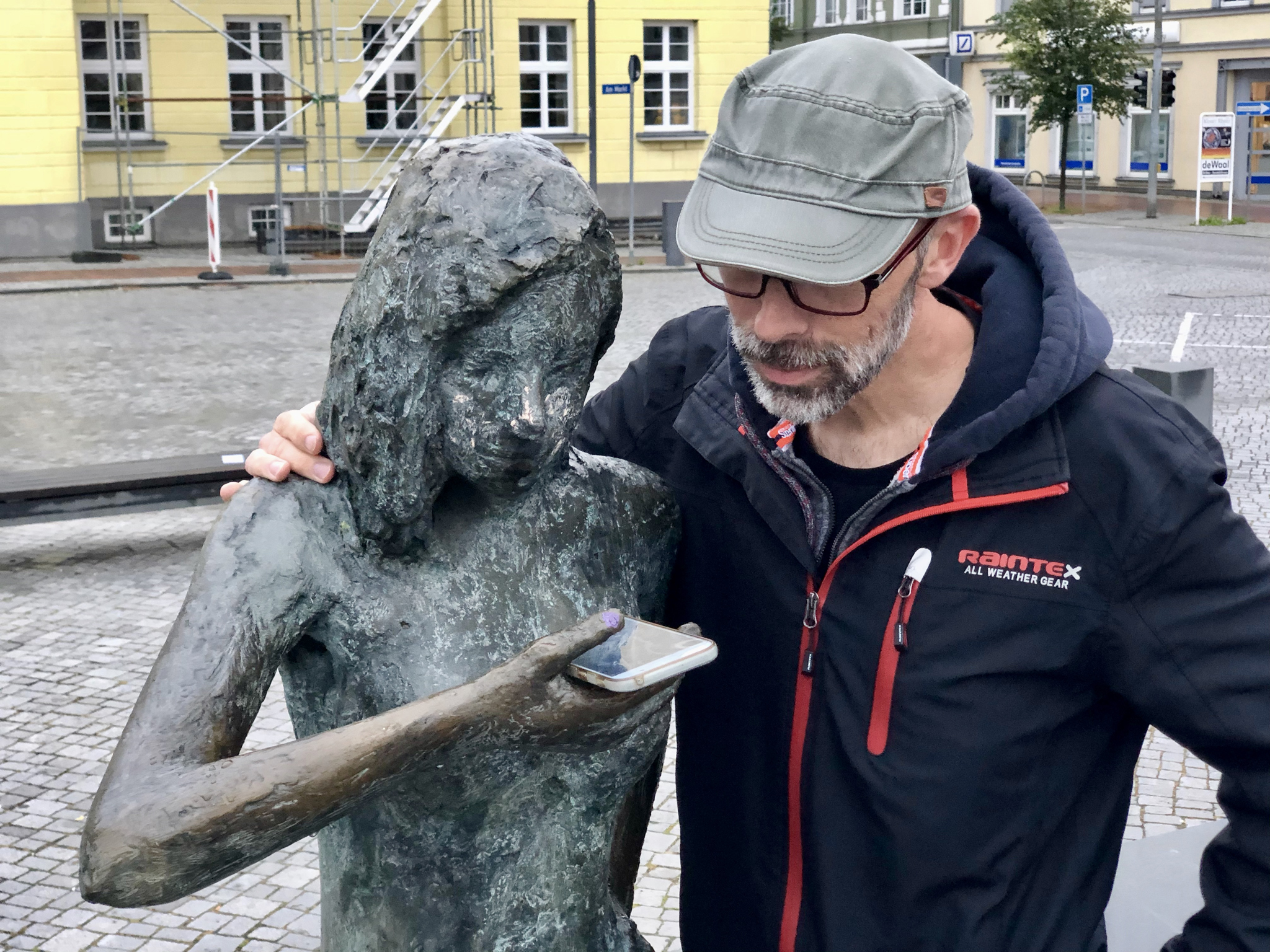
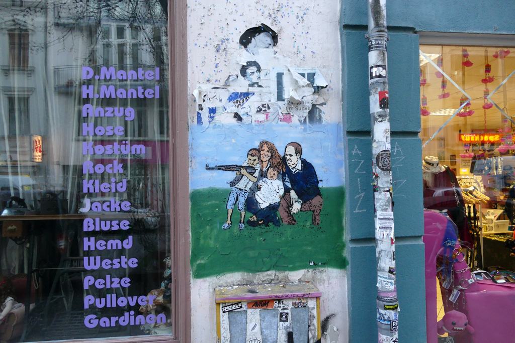
The green line also leads you through the rue du Maréchal Joffre. This small, trendy French street includes a baker, hairdresser, bookshop, burger joint, which is no surprise, but if you look up a little you will find that things are on the move. Over the hairdresser’s shop, there is a barber with that curious critical pose which is so typical of his trade, all the while his scissors snipping incessantly. In the base with its transparent cover, a giant comb moves back and forth. Over the vintage clothes shop a woman keeps trying on the same red and white spotted dress, the gearwheels of indecision spinning beneath her feet. All along the street there are a good dozen of these creations, which can be seen during the annual event held in France’s 6th largest city, Nantes which is near to the Atlantic coast and the Bay of Biscay.
The automata were designed by Nantes-based English artist & illustrator Gavin Pryke. He is quoted as saying “I like the idea of making an interactive work that appeals to children and their grandparents alike.” Implementation of the full size automata started in December 2014 with a team of 8 people involved in their production and installation. Installed above shops and restaurants they are quite large so that they can be easily seen and enjoyed from across the street. The bases are reminiscent of the bases of table top automata where turning a handle visibly puts cogs and levers in motion. In rue du Maréchal Joffre the real mechanisms are concealed and the bases have a transparent front revealing mechanisms which are part of the show but do not actually make things move. It’s a hard life as an outdoor automaton, so they are only installed for the duration of the Voyage à Nantes event during July and August. At night the wooden performers are allowed to rest, to get ready for their next action-packed day. After the event they are taken down and moved indoors for some tender loving care to make them fit and ready for the next year.


 The swinging man has to really enjoy his swing as he is in 7th heaven, so moving forwards he leans back and pulls his legs up with his mouth open laughing. Right at the back, ready for his next swing, he sits up straight with his mouth closed and his legs hanging down.