The Idea
The way that groups of fish move together has always interested me (flocks of birds too, but that is another story). Occasionally I see underwater nature TV programmes which show how a school of fish move like synchronised swimmers or a group of ballet dancers moving together across a stage. I found one definition of a “school” as a shoal of fish swimming in the same direction to then suddenly all change direction at the same time. My question was – how do they do that? Is it telepathy? Is there a sergeant-major fish who yells “about turn!” So I thought why don’t you make yourself a school of fish and see how you can make it “school”, or dance yourself.
Inspiration
Before making anything, I always have a look around hyperspace, to see how others approach the same challenge. It’s boring to simply copy someone else’s work, but seeing what approach they take and how the finished item works out is always an education and often an inspiration. Entering “fish automata” into a search machine, I found quite a few matches. Two impressed me in particular: one with just a nice single fish by Carlos Zapata (https://cabaret.co.uk/fish-2012-by-carlos-zapata/) and another quite complex one with a big school of fish by Matt Smith (https://www.youtube.com/watch?v=CGaj_KlXFqs).
Approach
Trying to keep things as simple as possible, I thought maybe I could use a cam to make the fish wiggle. I then decided to let the operator choose in which direction the fish should swim instead of automating a fixed routine of direction changes. Simply turn the crank one way to swim left and turn the crank the other way for the fish to swim right. The operator of the automaton then becomes the choreographer for our fish ballet school.
Drawings
I used the Graphic app on my computer to produce scale drawings. This took up most of the time as I kept modifying things as I noticed where bits might bump together, or where gravity might pull parts in the wrong direction. It is hard to follow drawings which you didn’t draw yourself, but together with the photos they should make some sense.
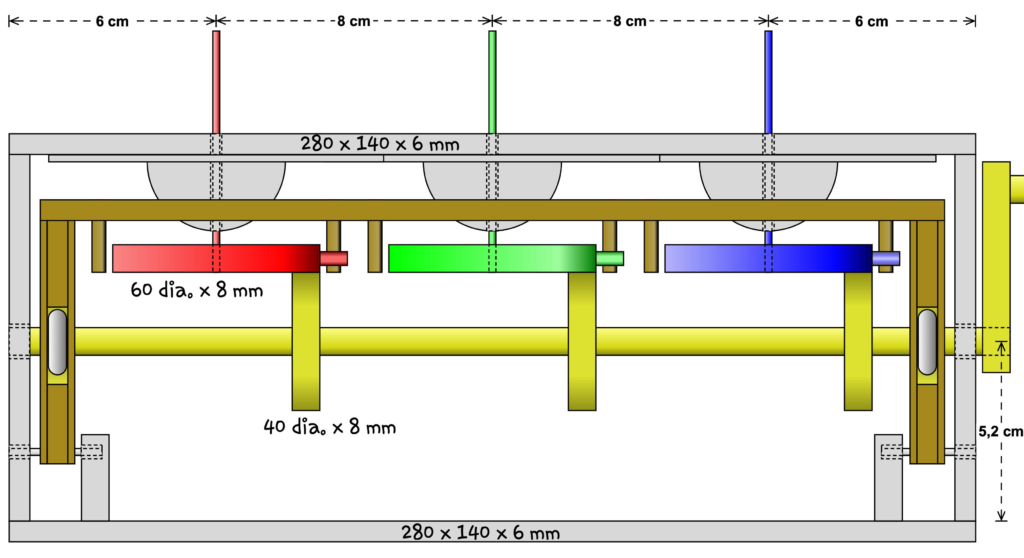
For the drawings I used a different colour for each moving part.
– The yellow part is the crankshaft which is turned by the operator.
– The red, green and blue parts each carry two fish at the top (not shown).
– The brown part (the wiggler) holds the stops which limit the movement of the red, green and blue discs.
– The grey parts are fixed and don’t move.
As the camshaft is turned, the three yellow wheels drive the red, green and blue discs, turning them until they encounter the stops on the wiggler.
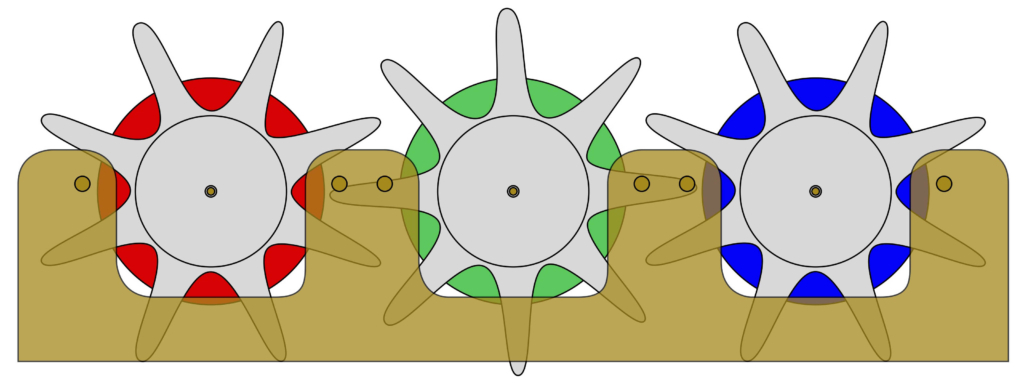
The top view follows the same colour scheme but doesn’t show the crankshaft or the box. The grey circles represent wooden hemispheres which act as lengthened bearings for the brass rods, which each hold two fish. I thought these looked like upside down octopus so, to reinforce the effect, I added a 3 mm thick set of arms to each one, which accounts for the odd, grey star shapes. The six small brown circles in the wiggler show the 3 mm dowels which protrude downwards to act as stops, limiting the rotation of each coloured disc.
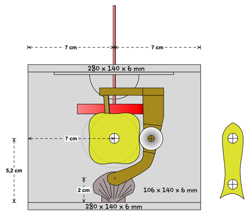
The side view shows the yellow cam responsible for wiggling the fish, four times per rotation. The brown part is hinged at the bottom and a free-running wheel ensures smooth movement as the cam turns. Imagine the cam pushing the wheel and thus tilting the brown part outwards, towards the front of the base. This moves the stops towards the front. The low points on the cam allow the stops to move back towards the rear, encouraged by a spring (not shown).
The fishy, yellow part to the right is part of the external crank which the operator turns.
Templates
One of the advantages of producing drawings is that you can print out and then cut out templates, which speeds up things in the workshop.
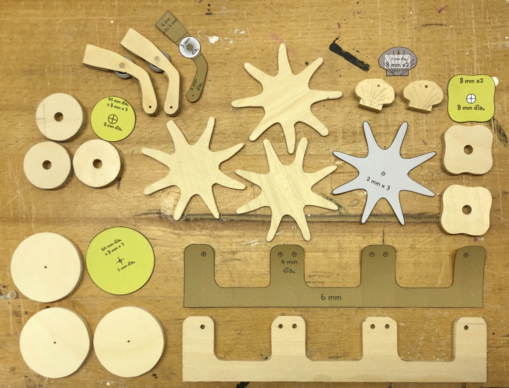
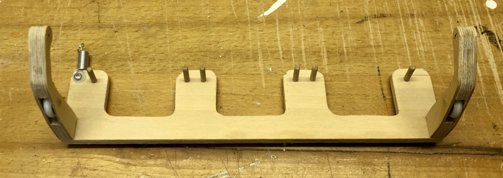
Base – top
This is what the underside of the top looks like.
The purpose of the hemispheres is to lengthen the bearings (holes) in which the long brass rods sit. The rods must turn easily in the bearings but should stay vertical. Longer bearings keep the rods straighter whilst still allowing them to turn freely.
Brass rods to hold the fish
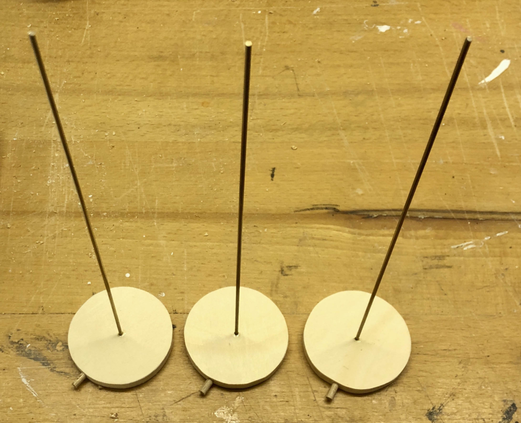
Here are the large discs responsible for turning the fish with pieces of dowel protruding from the edge which restrict the amount of turn, when they hit the stops on the wiggler. The long brass rods are carefully fixed, vertically, into the discs using two-component epoxide adhesive.
The camshaft
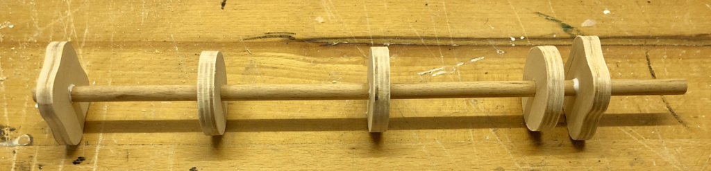
The camshaft has two identical cams at each end and, between them, there are three drive wheels, each driving one of the discs on the end of a brass rod.
The wiggler
This strange looking thing holds the stops to restrict the rotation of the large discs. It is hinged near the bottom of the base and the spring pulls it against the two identical cams. As the cams turn they move this gently forwards and backwards. The slight movement of the stops causes the large discs to move a little, which in turn make the fish wiggle a little. It is the wiggler.
The assembled mechanism
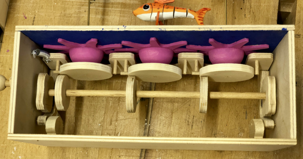
When assembled, the stops on the wiggler are positioned so that they can catch the protruding dowels in the edges of the large discs. For each disc there are two stops. One restricts clockwise movement, the other counterclockwise movement.
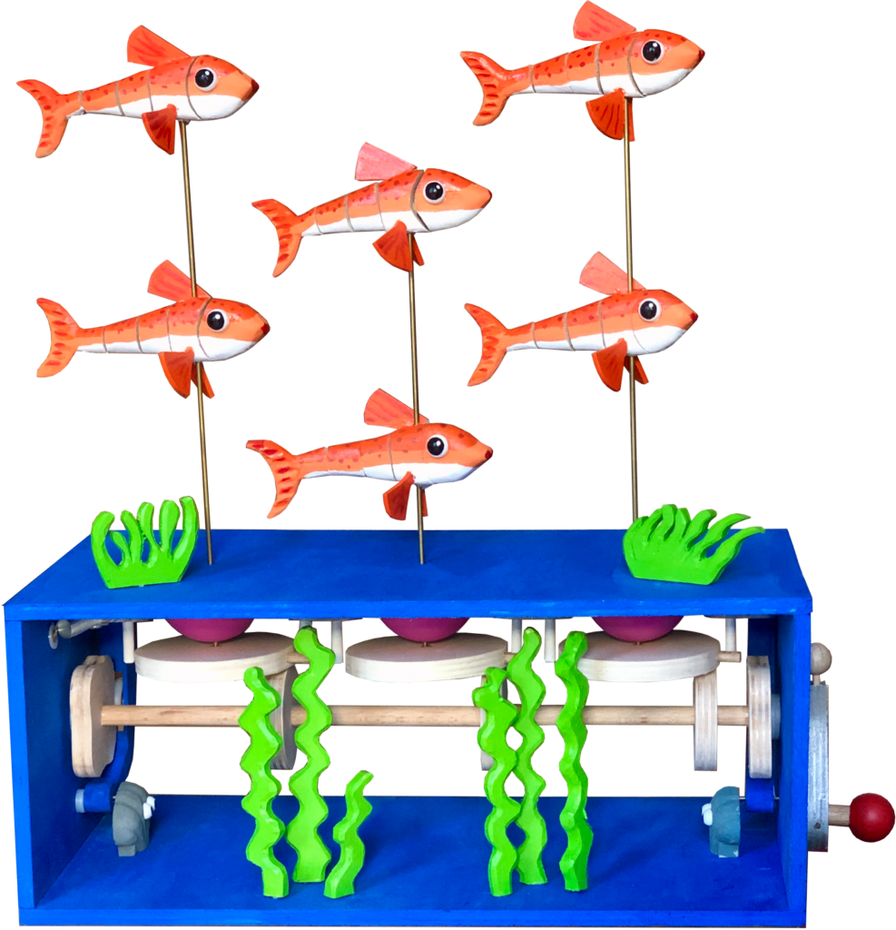
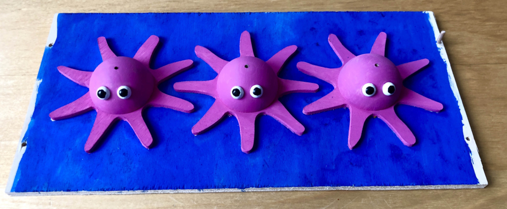
The fish
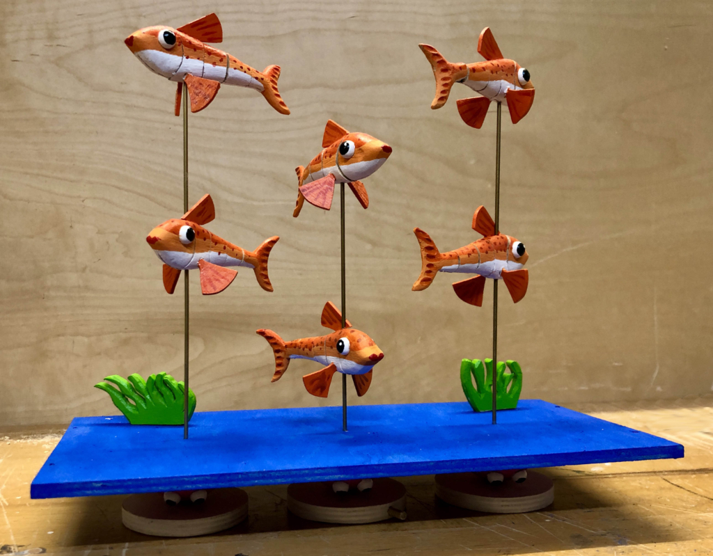
I carved the fish from lime wood and added fins made of 3 mm plywood. After cutting each fish into four pieces, I used a fretsaw to cut a slot upwards in each piece, making space for a piece of flexible tape. Some careful gluing later and the fish wiggle in quite a fishy way. Two fish are mounted onto each brass rod using two component epoxy resin adhesive.
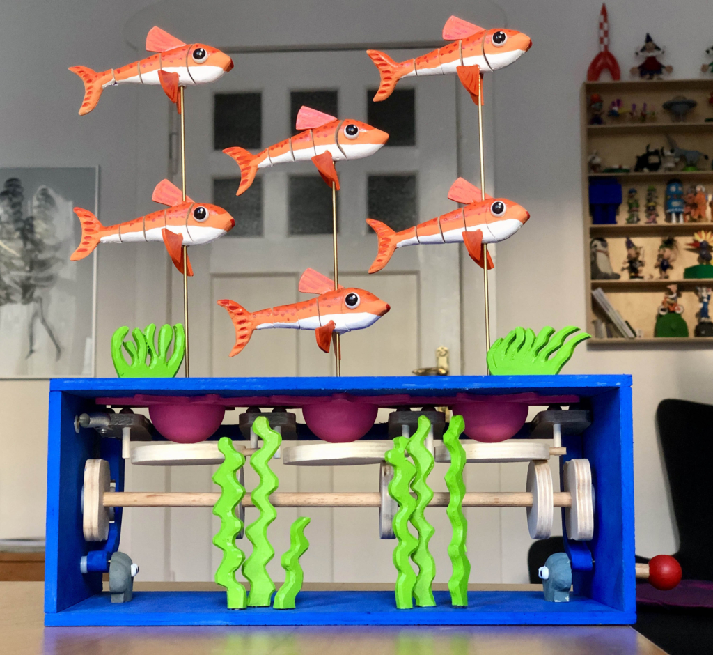
The painted base
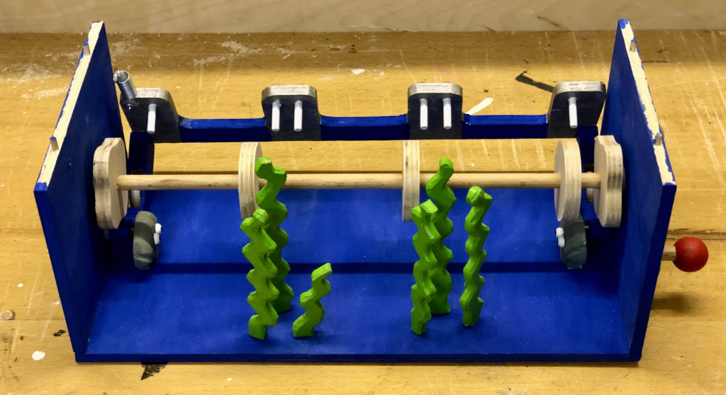
Some underwater vegetation builds on the aquatic atmosphere, as does carving the supports to hinge the wiggler as clams. My clams have eyes which makes them a species as yet unknown to science. As the spring is not fixed here, gravity pulls the wiggler away from its intended working position.
Final assembly & reflections
For this project, with an eye on future repairs, I chose to not glue the box together. Instead I used 3 mm dowel to pin the parts together while doing the fine tuning and painting. Once painted, I used brass screws to more permanently hold things together. Making things of wood is great, but wood does react to the moisture levels in the air. This has occasionally caused some of my fully glued creations to jam up, and repair then means having to destroy certain parts and then remake and repaint them.
Leaving the box without a front or back wall leaves the mechanism clearly visible for the many curious.
This looks quite complex, but there is not much to it with just a few moving parts. I now even suspect that one cam would probably have been enough to move the wiggler, making it even simpler.
When my seven-year-old quality control expert tried it out, she played happily with it for quite a long time. It is not really child-proof as the temptation to grab a brightly coloured fish and move it yourself is almost irresistible for small hands. The 2 mm diameter brass rods are fine for adults, but children would need something much more substantial. The fish are also not terribly robust. We will see what time shows. Other makers have used wire rings to join the fish segments together. Maybe that would be a bit sturdier.
Video
Download
Here are the images compressed for download. https://www.wordwise.de/Fish_archive.zip