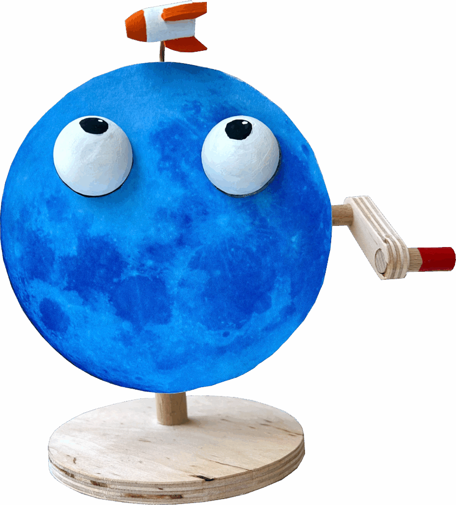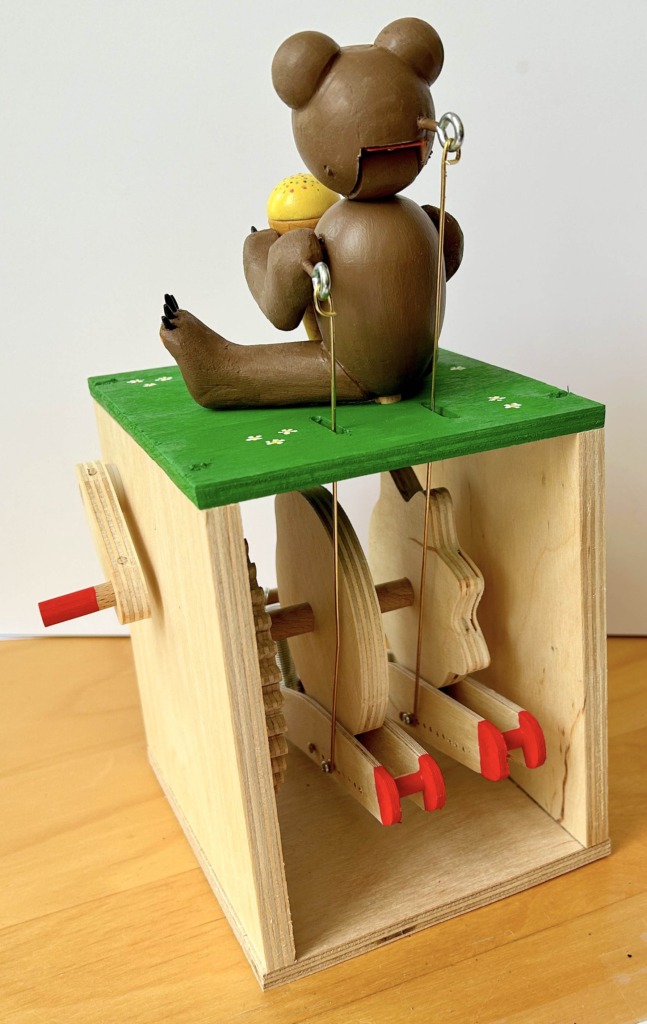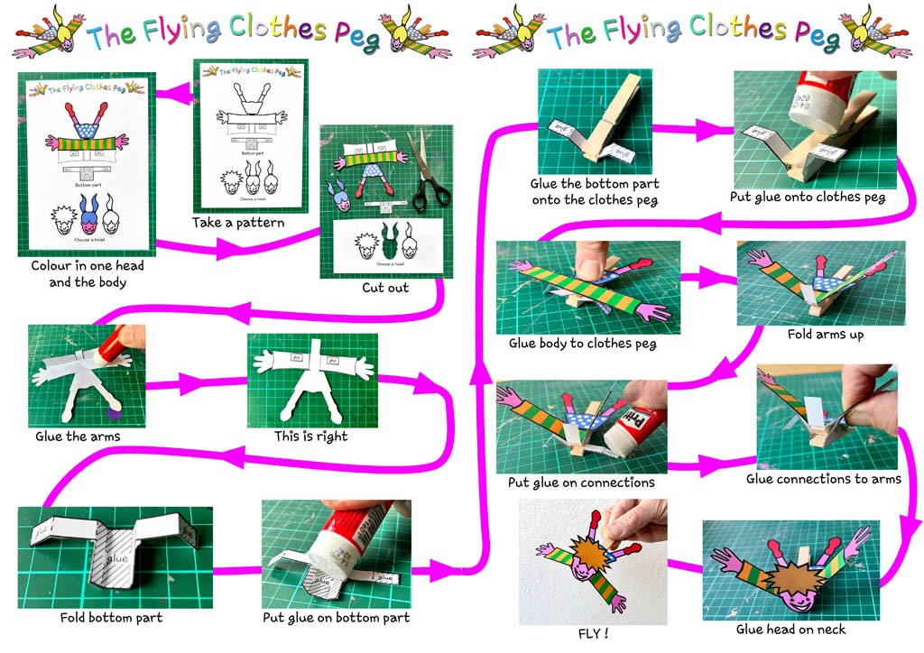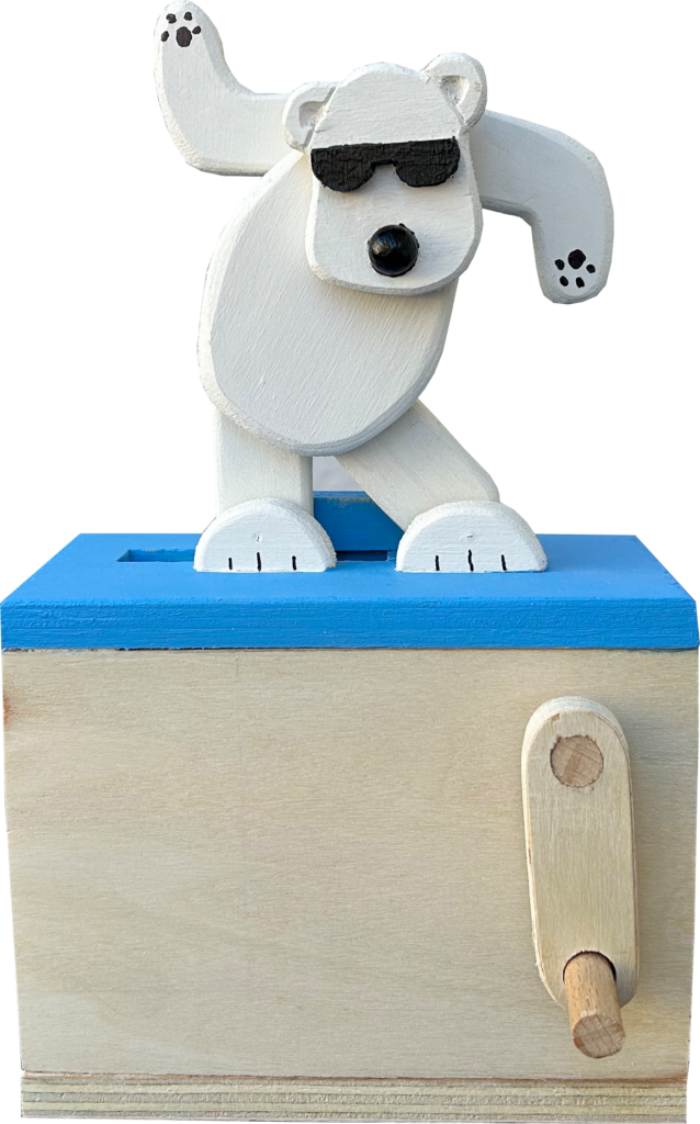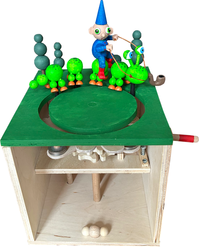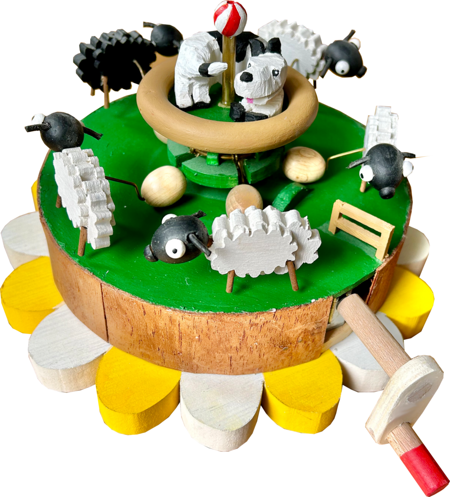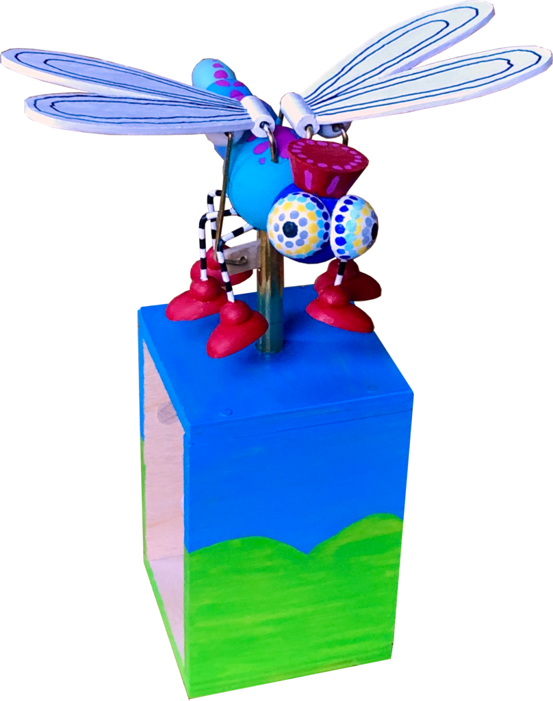
The Background
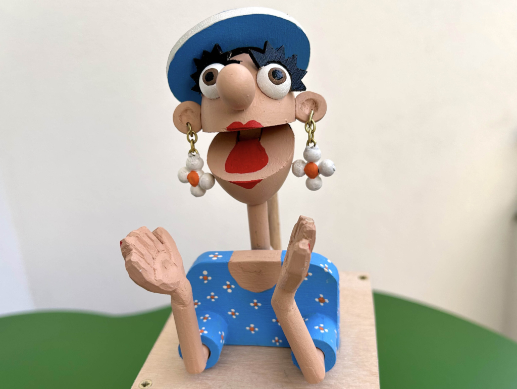
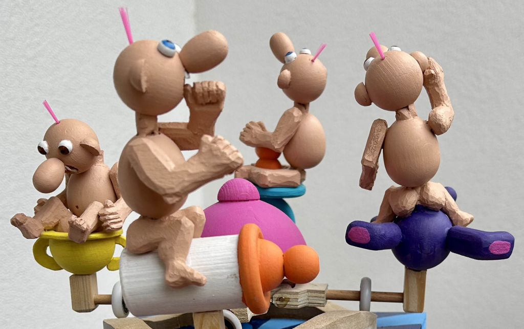
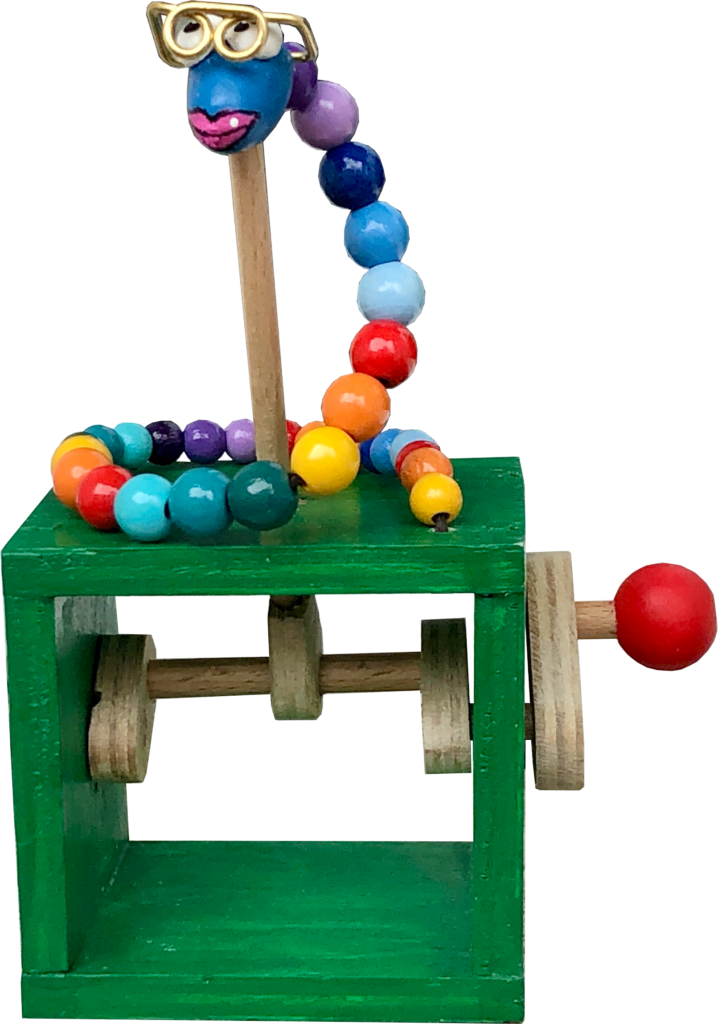
One day a friend was playing with the Happy Clapper automaton and she observed, not unkindly, “all of your figures have short hair”. She herself has long hair, as does her daughter and, when I came to think of it, all of her daughter’s girlfriends too. So why have I favoured short hair up to now? I guess the short answer is that it’s easier, when you make things of wood. I could have carved hair, but it never seemed likely to add much to the action. It’s the movement that is most interesting in automata so, if hair then it has to be moving hair. Moving wooden hair.
The Requirements
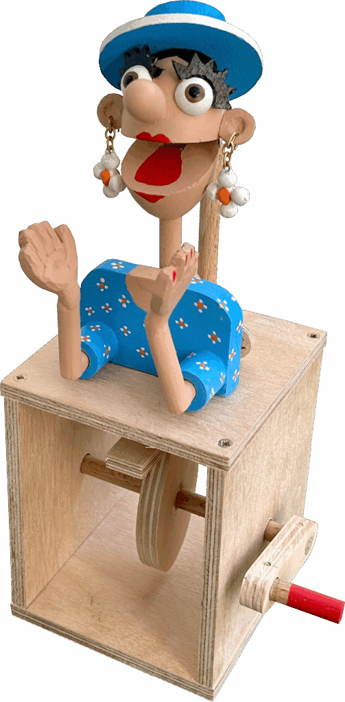
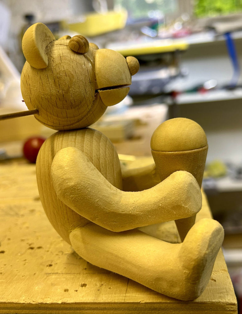
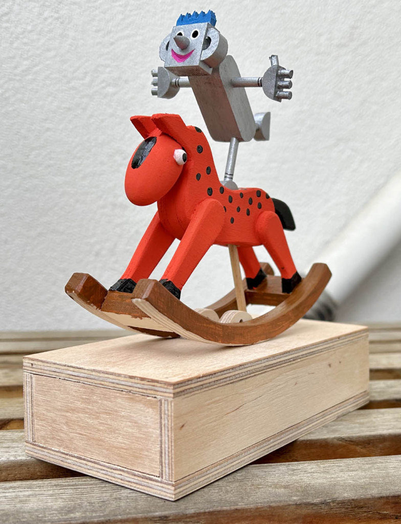
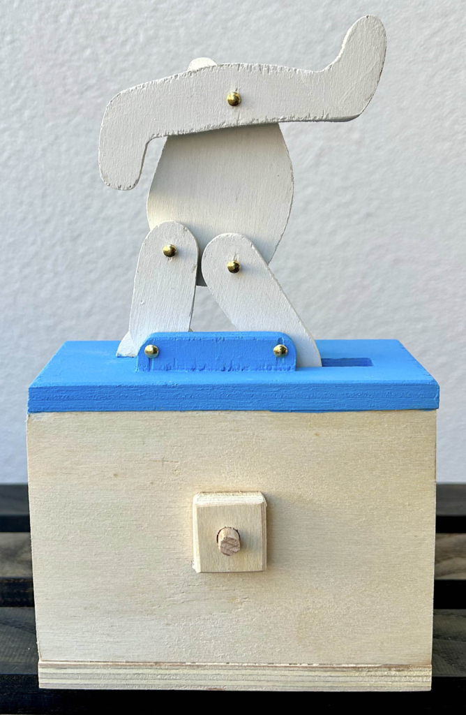
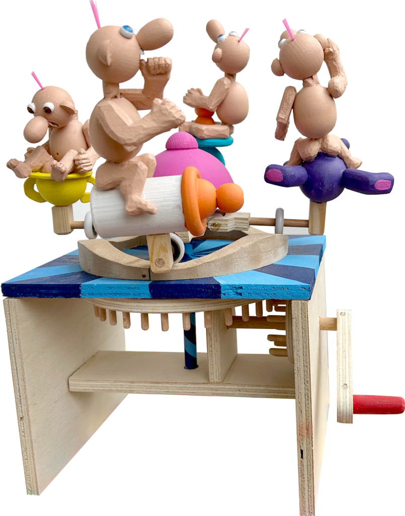
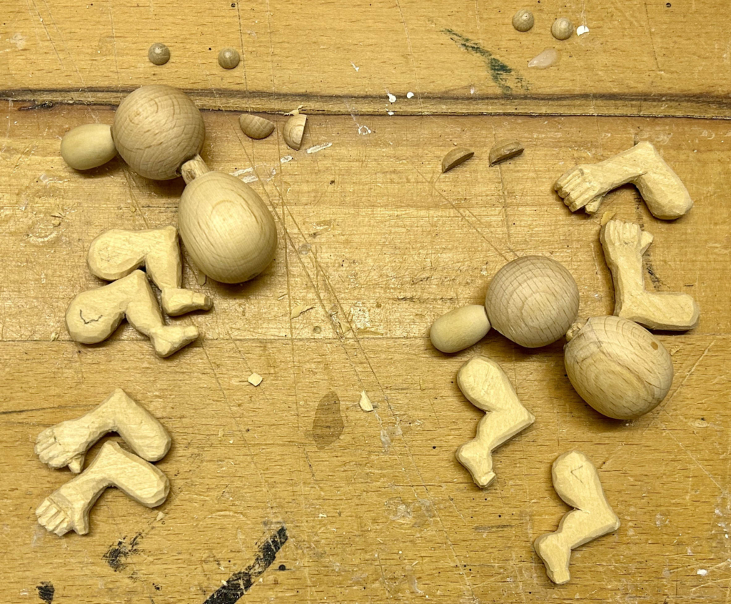
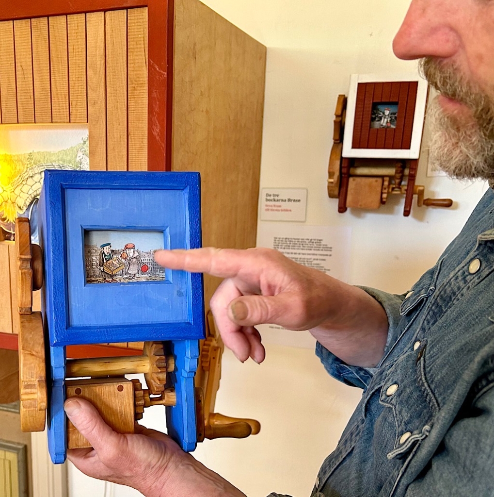
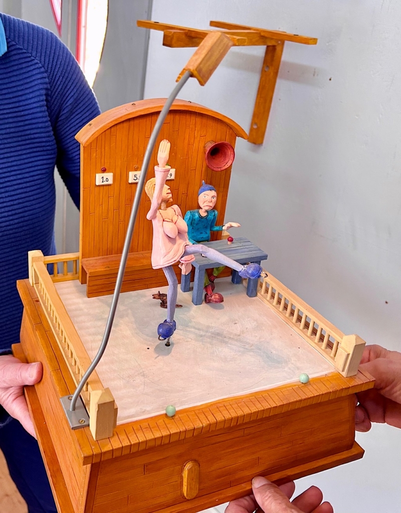
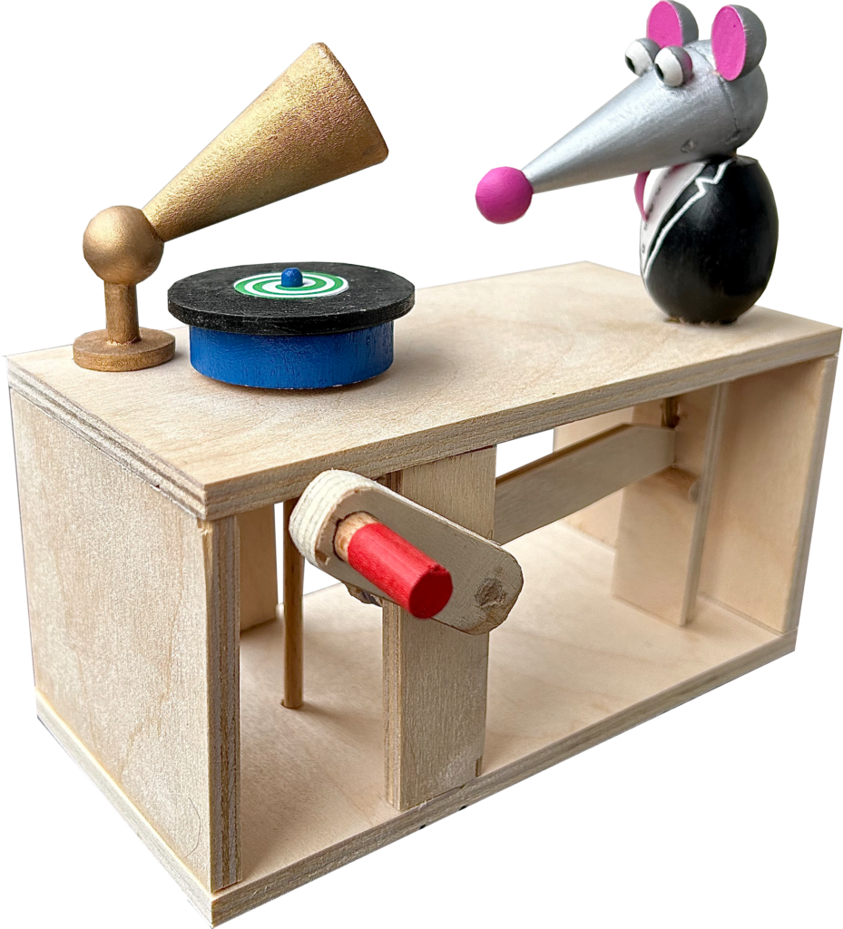
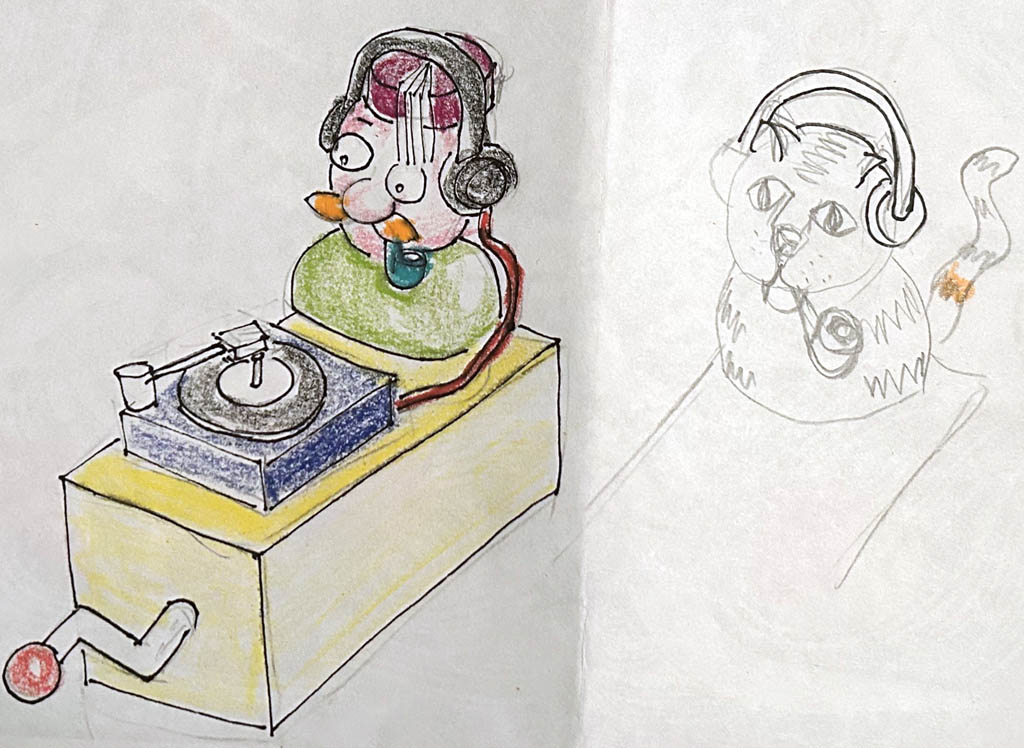
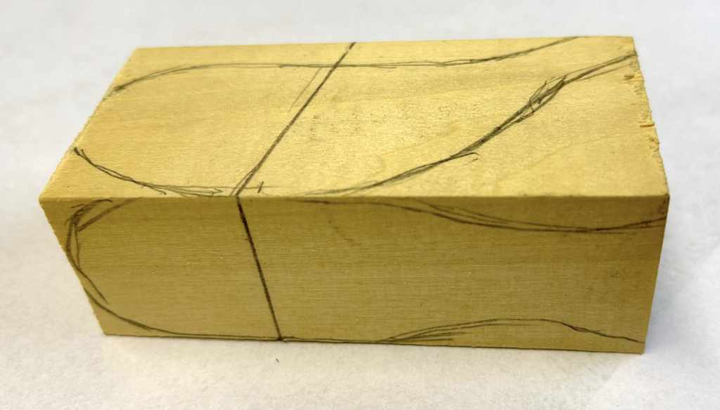
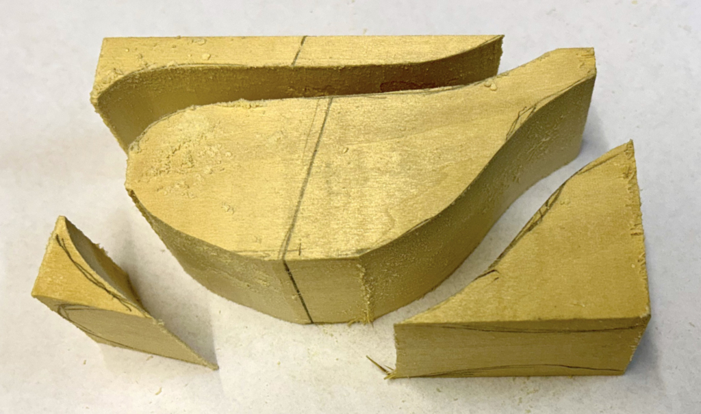
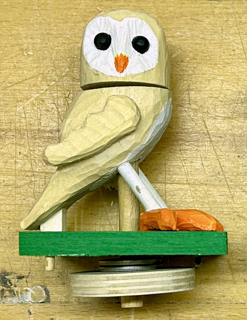
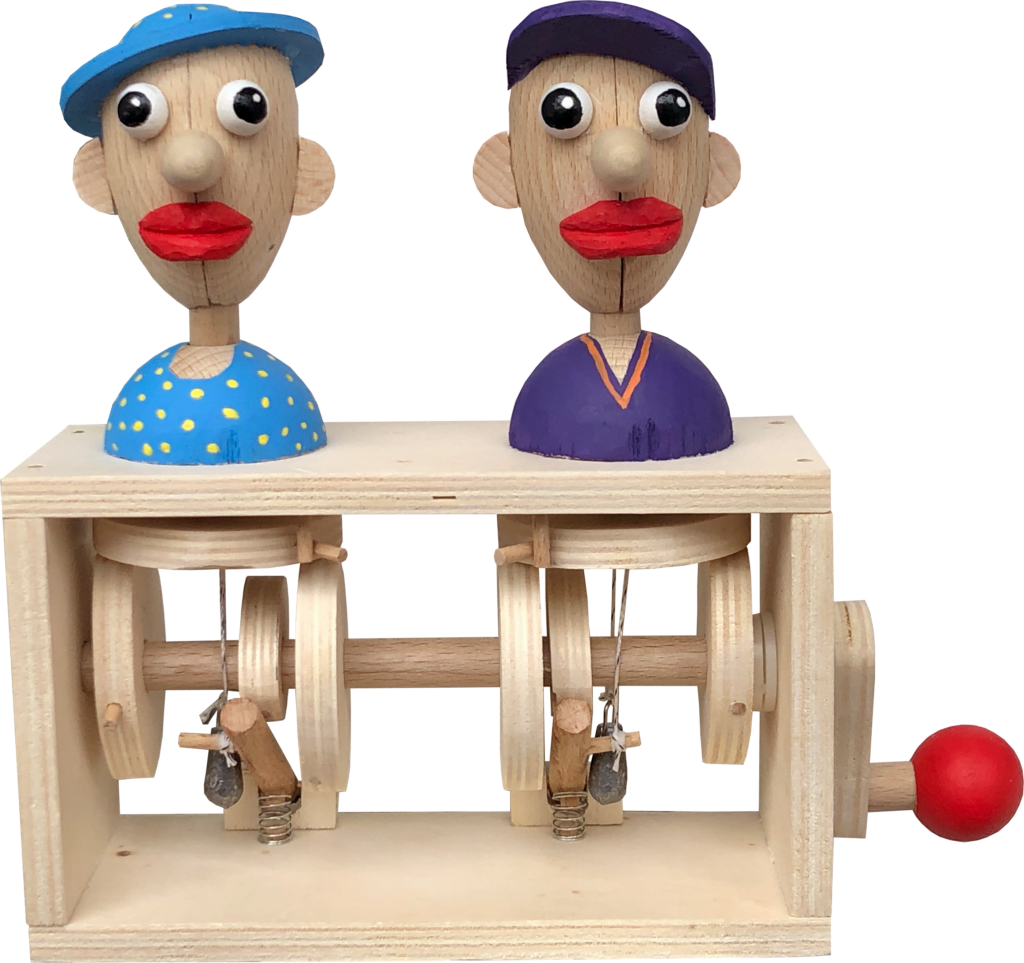
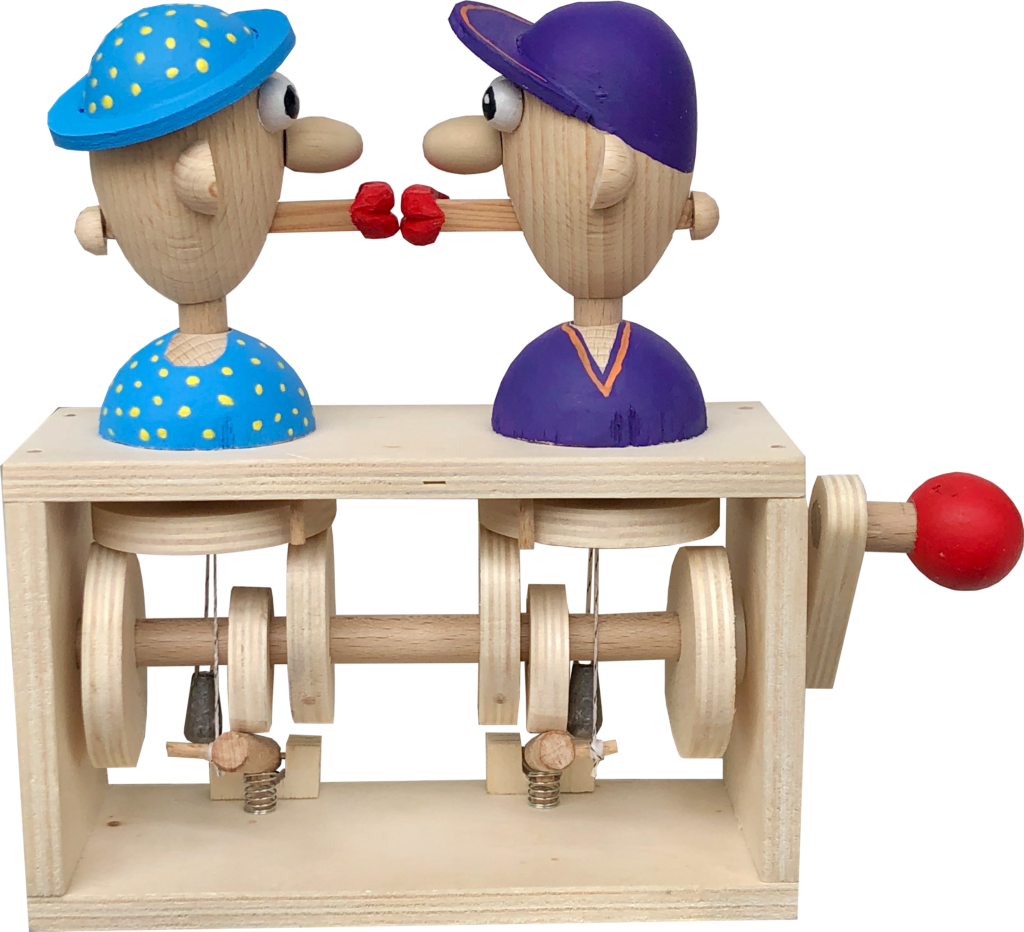
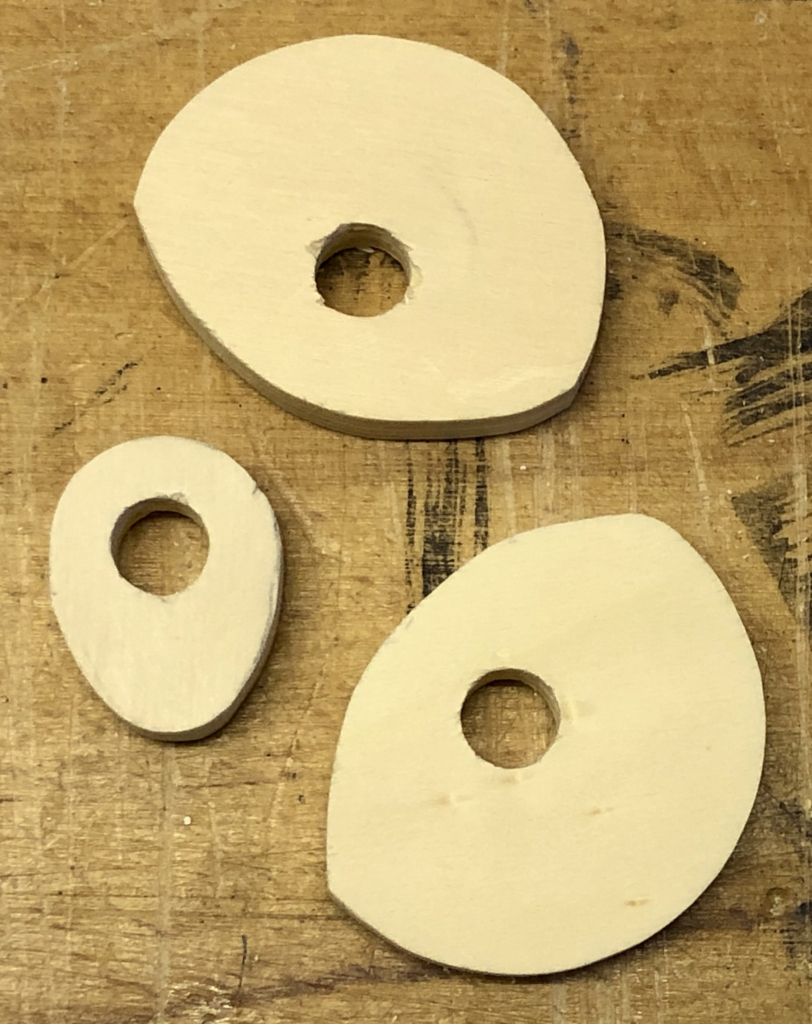
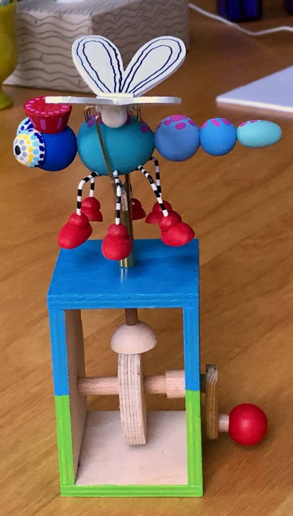
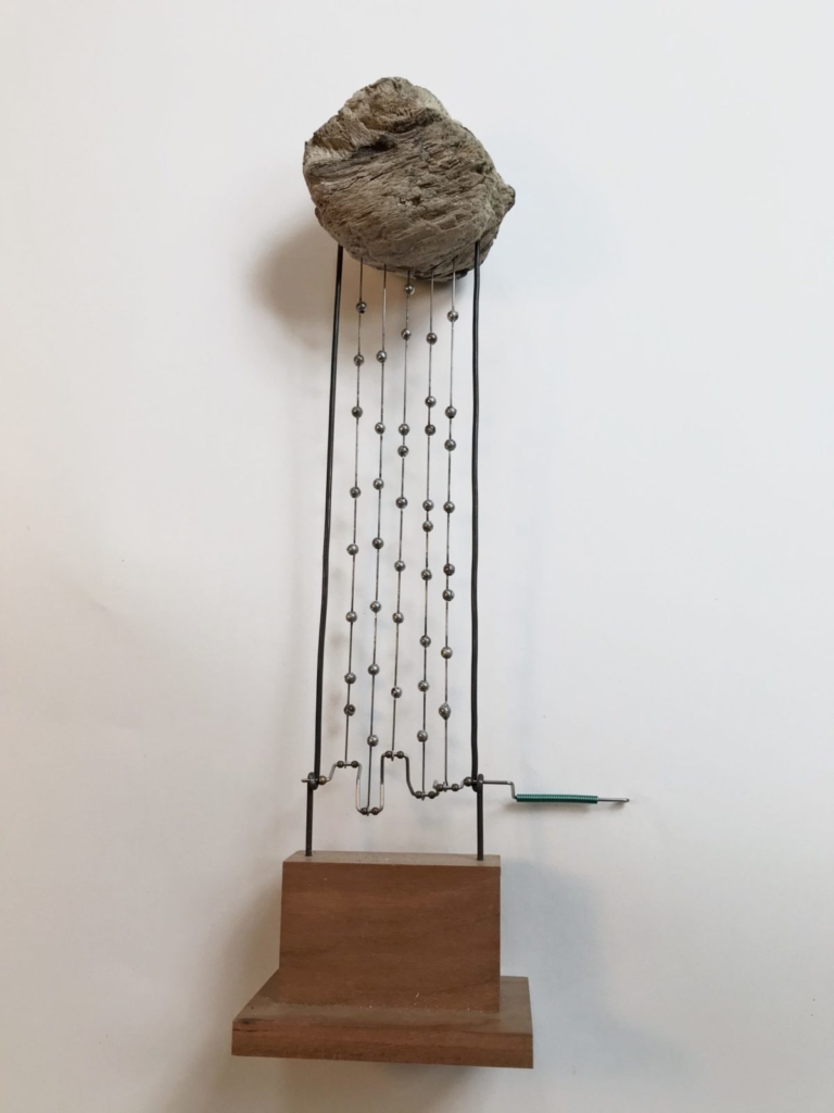
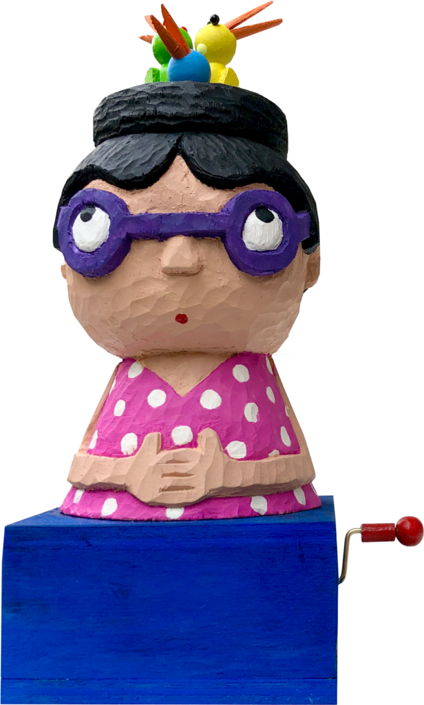
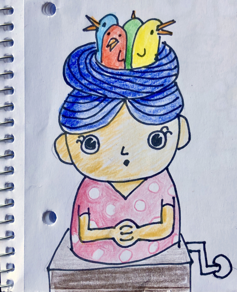
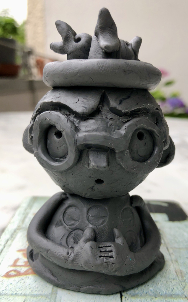
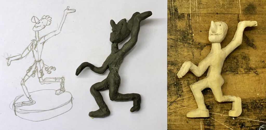
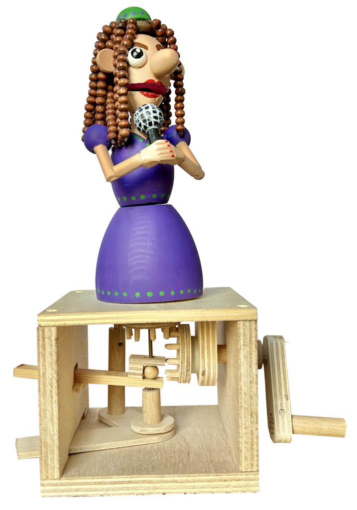
A singer seemed like a suitable vehicle to show off long hair, A musician singing a passionate song moves a lot so I decided to make a singer who can separately (1) open her mouth, (2) turn her head and (3) turn her upper body. To allow her to sing a range of different songs, I decided against a fixed, cam-driven, sequence of movements, instead opting for three separate controls for the three movements. To emphasise the singing a microphone seems about right.
The Hair
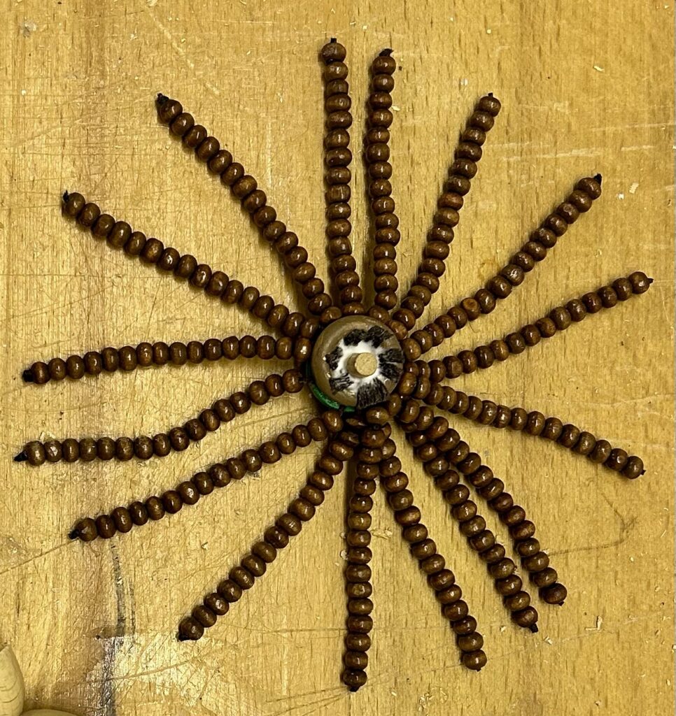
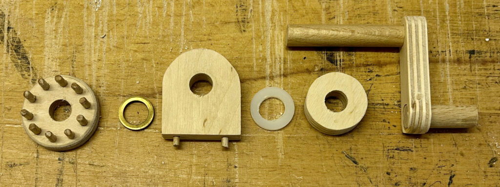
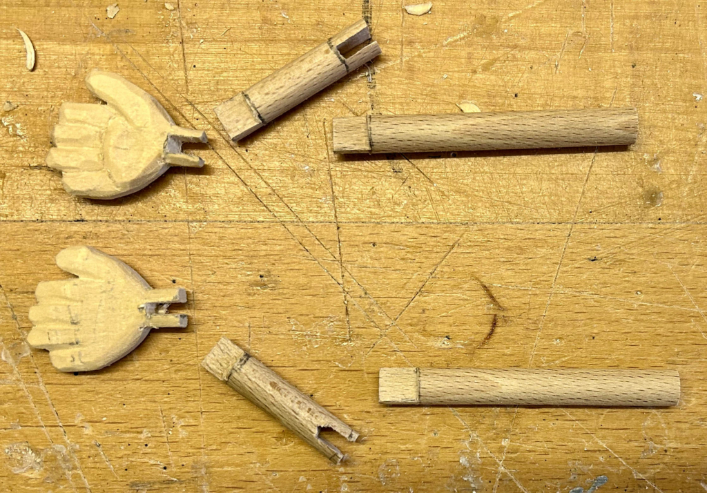
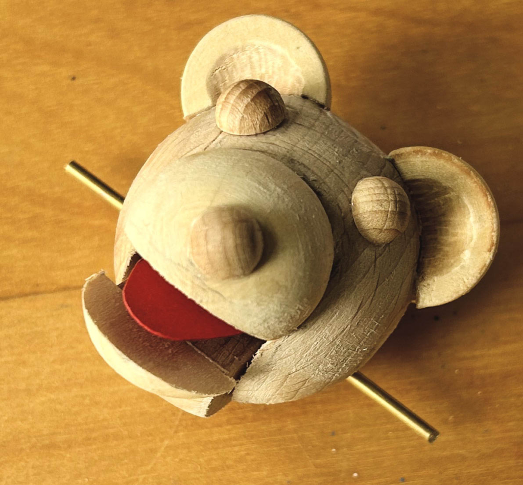
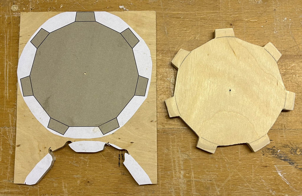
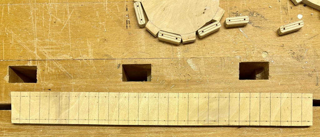
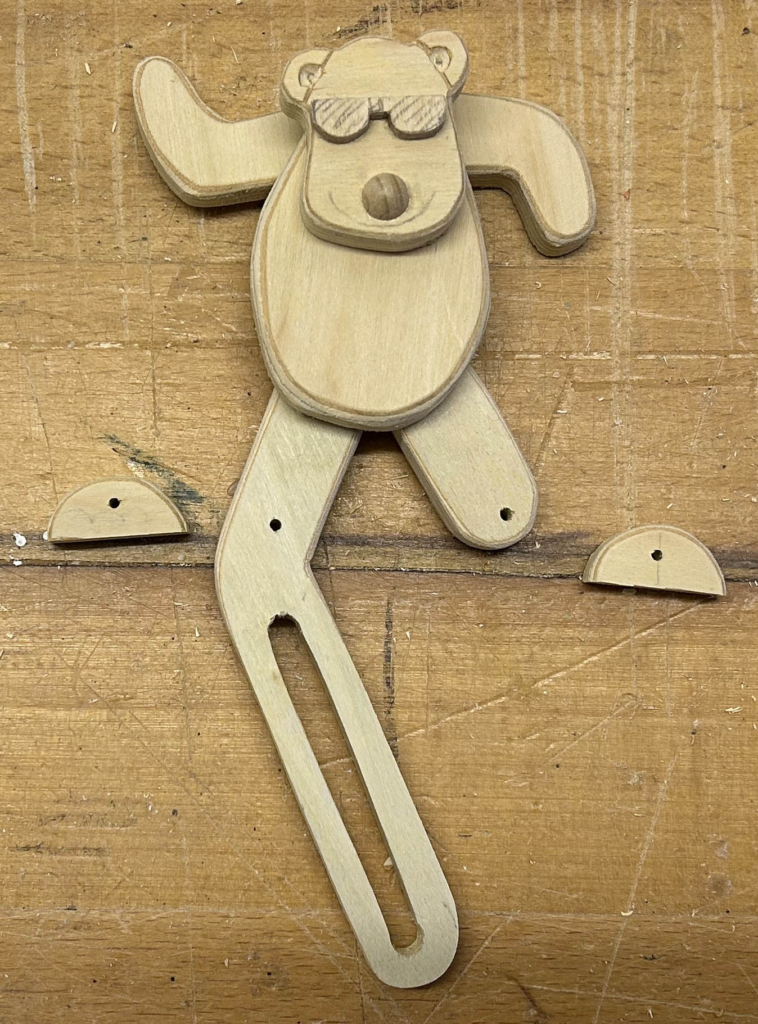
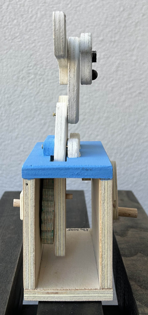
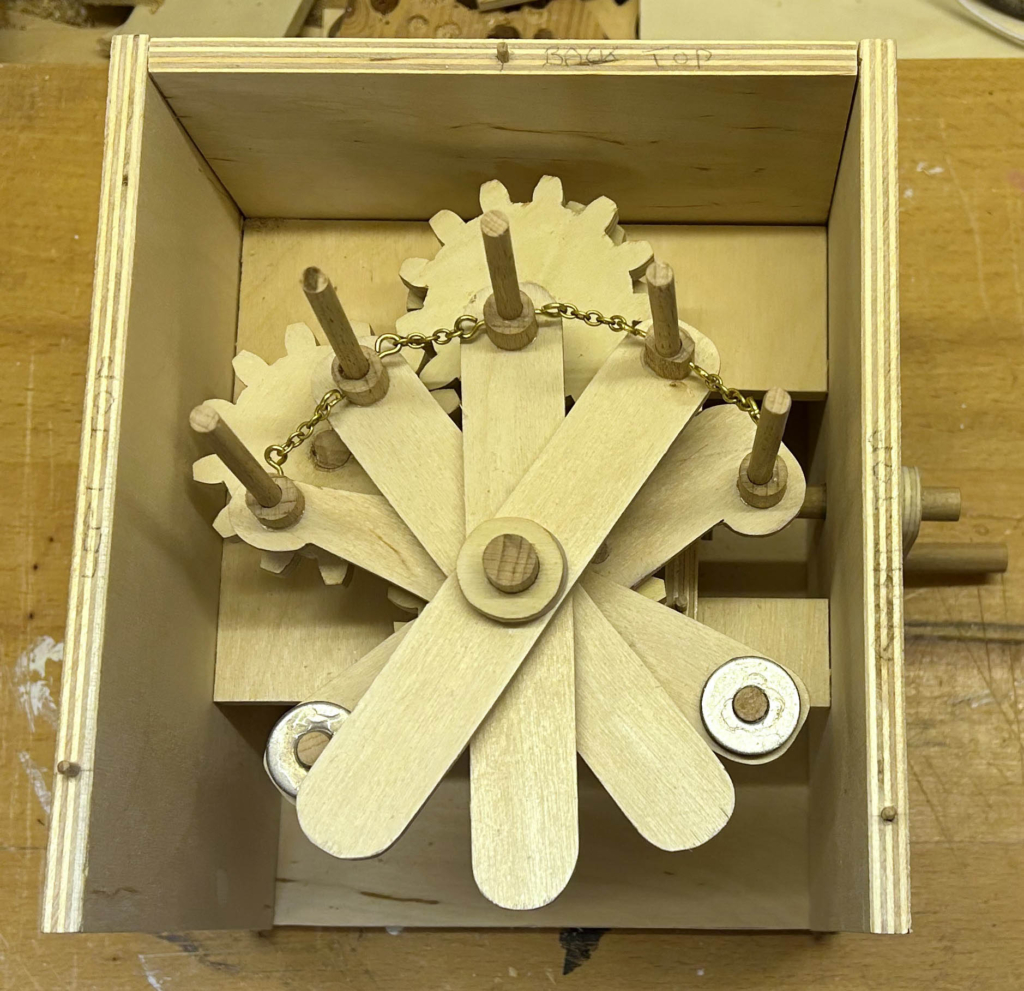
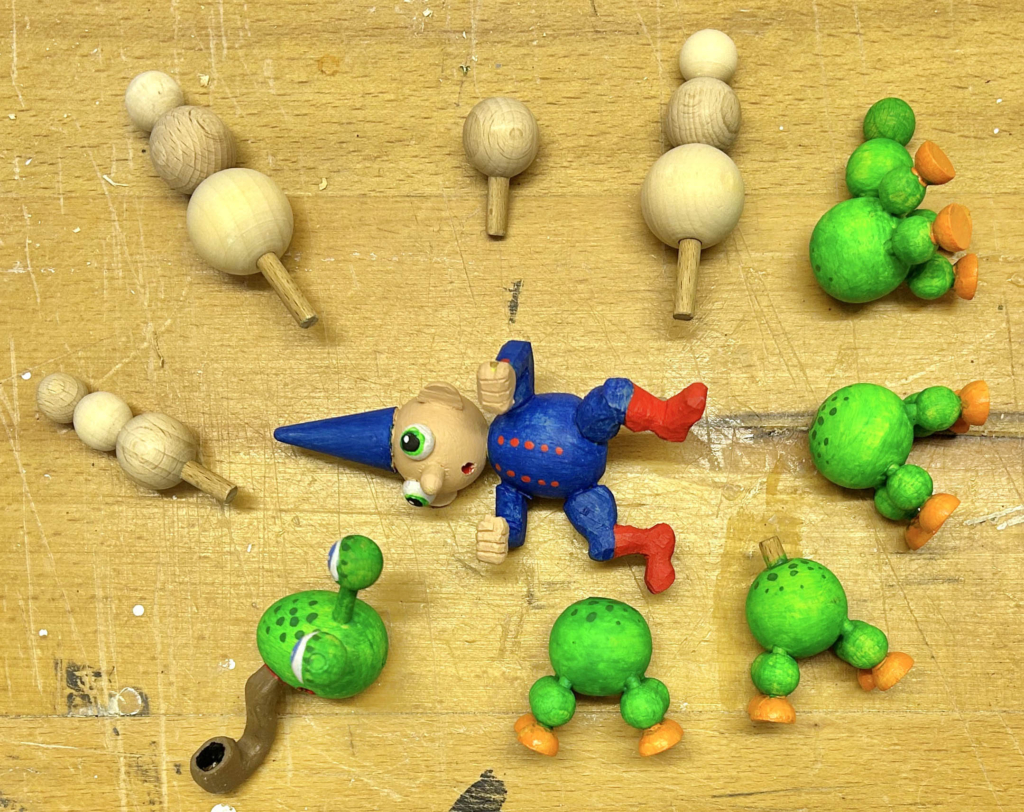
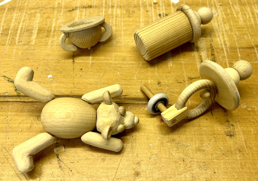
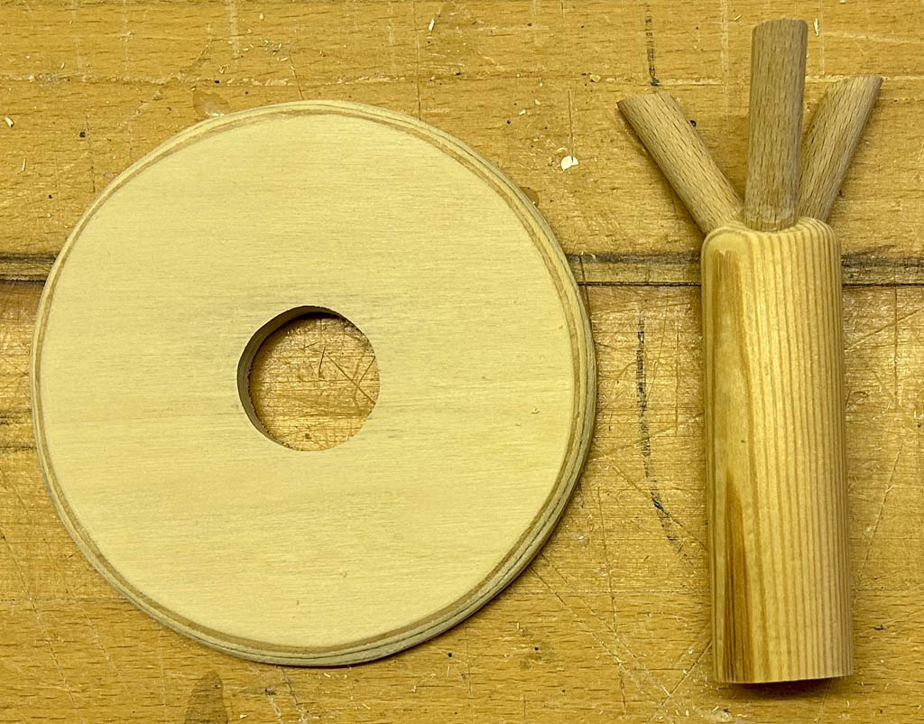
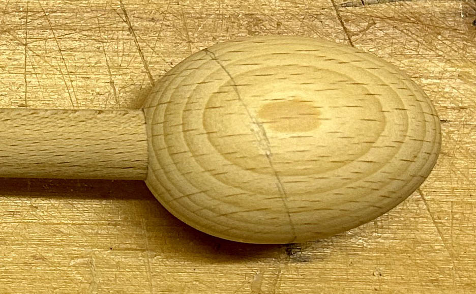
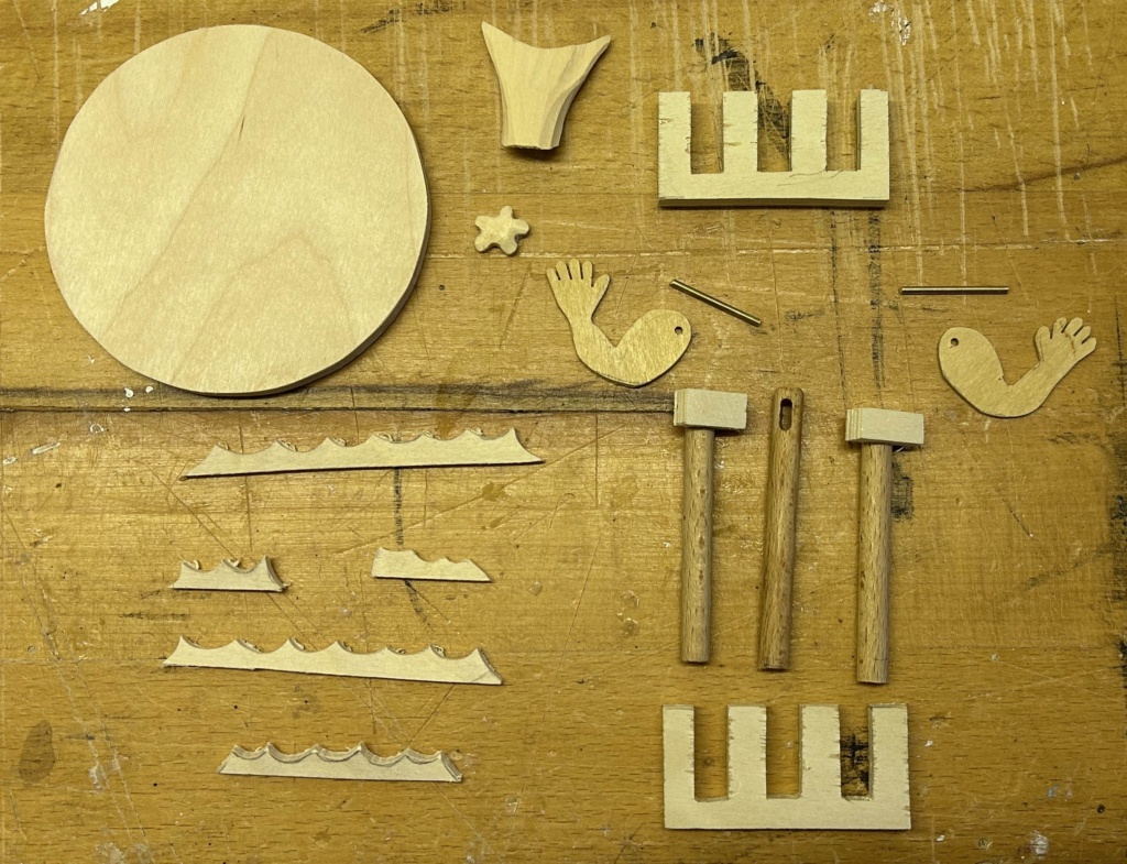
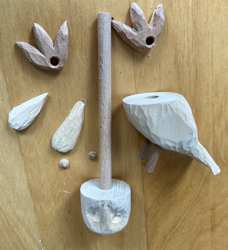
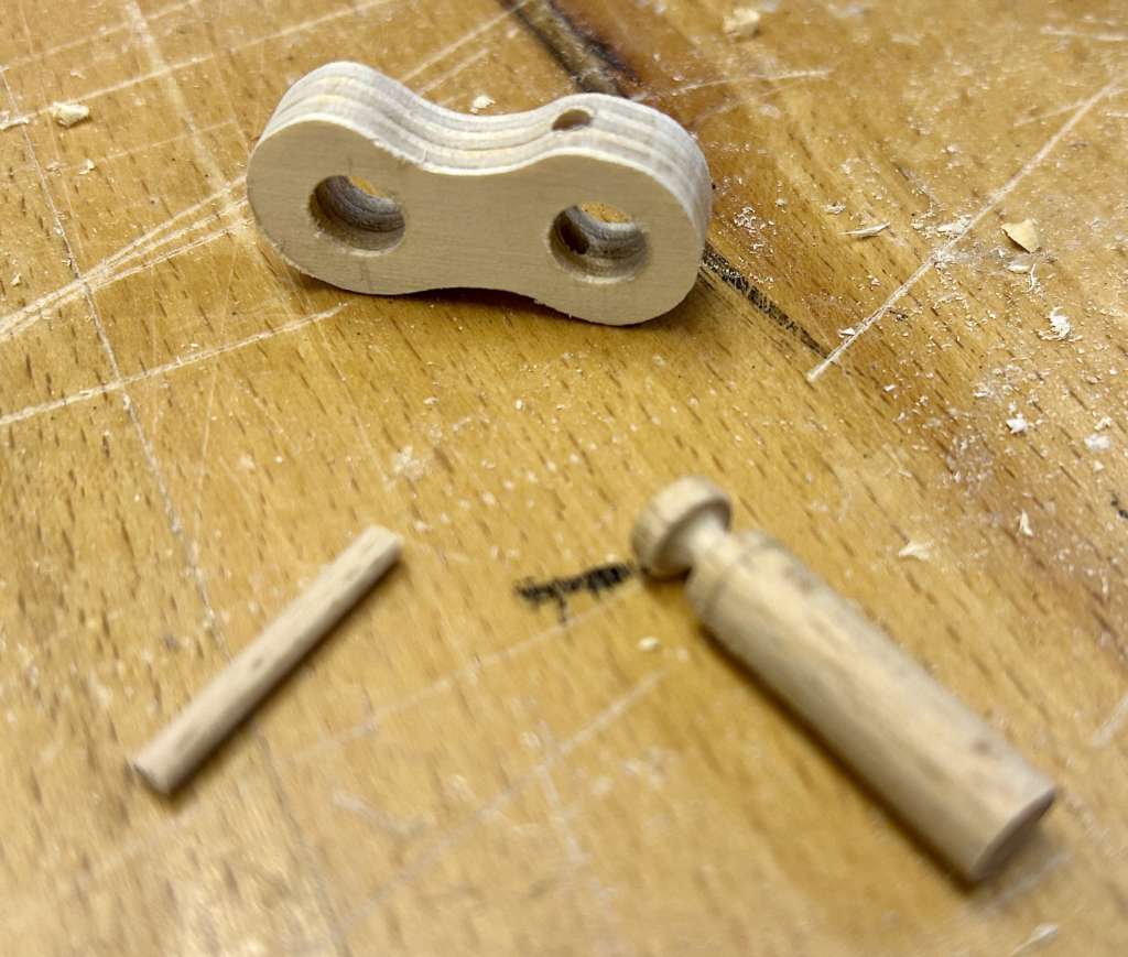
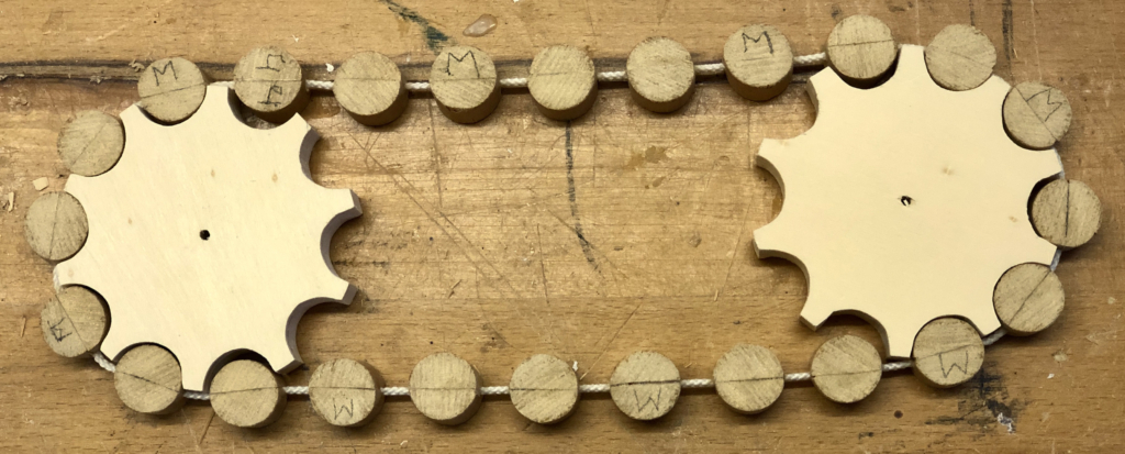
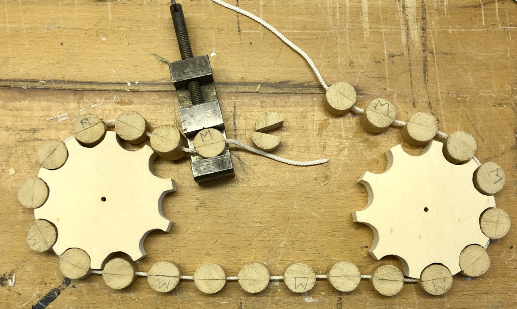
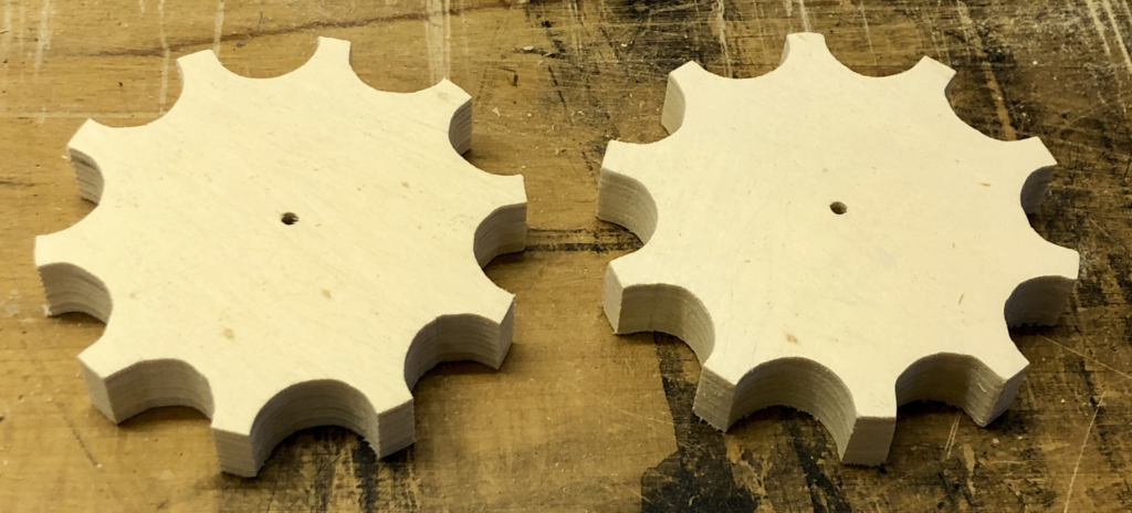
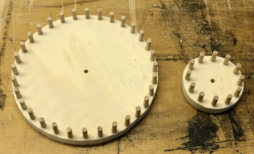
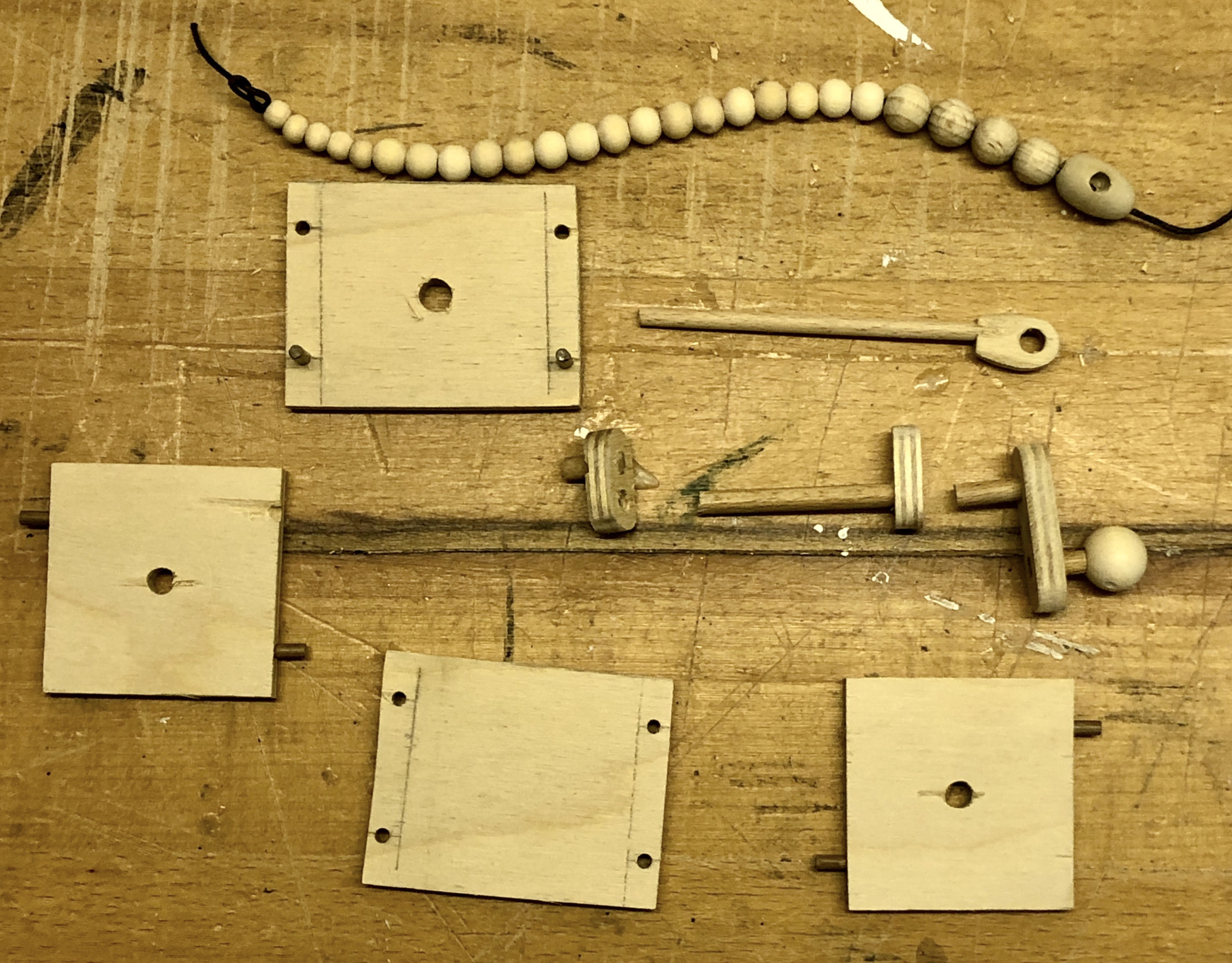
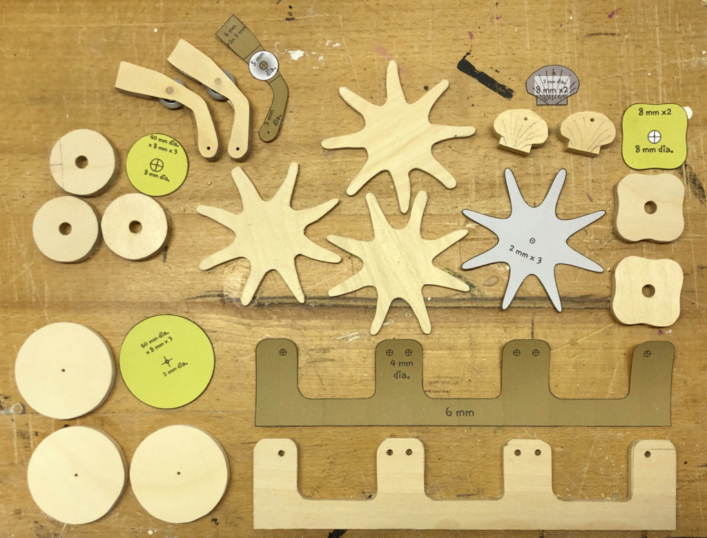
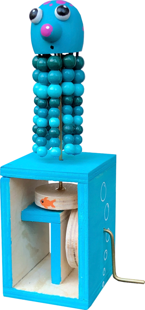
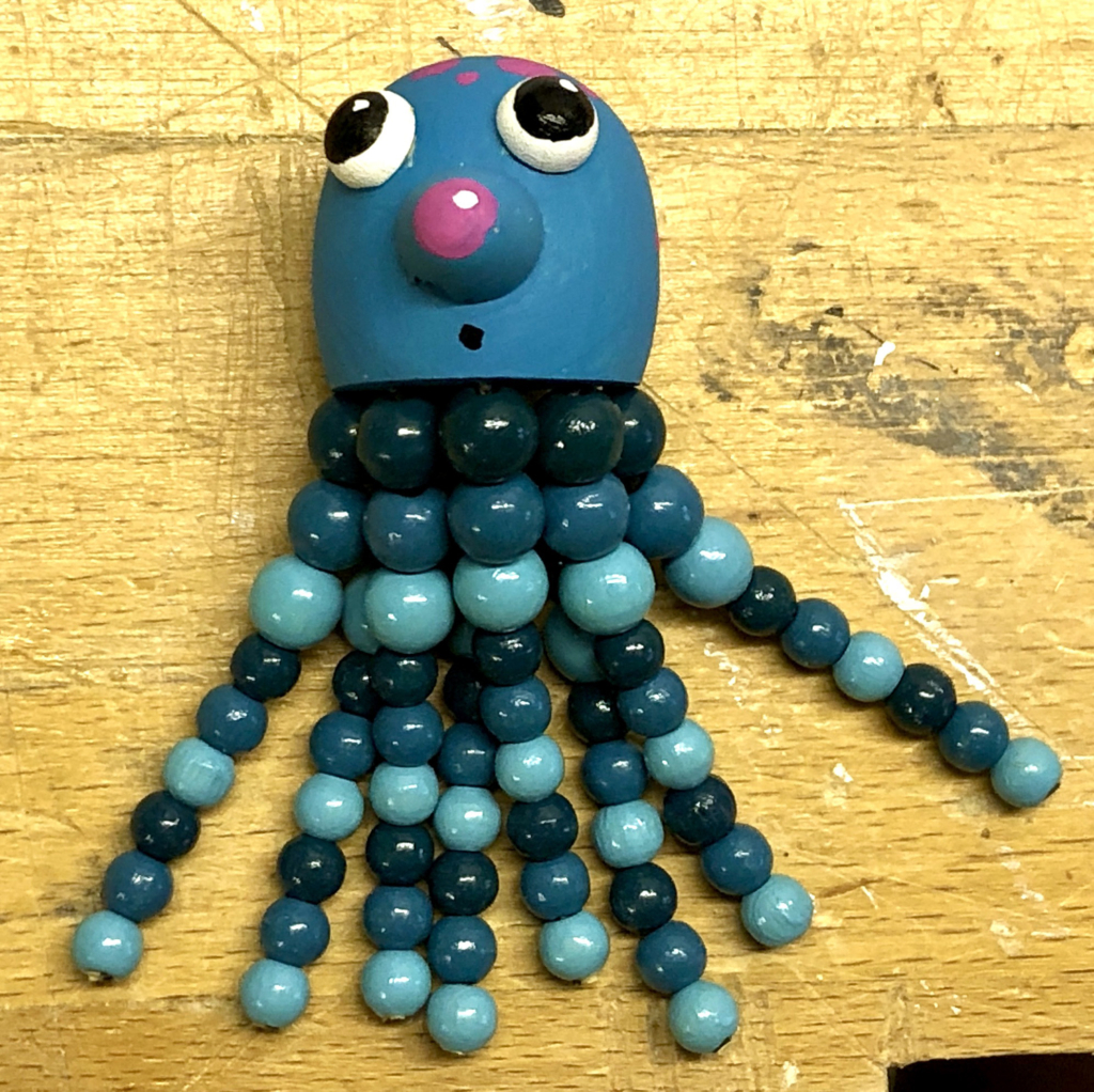
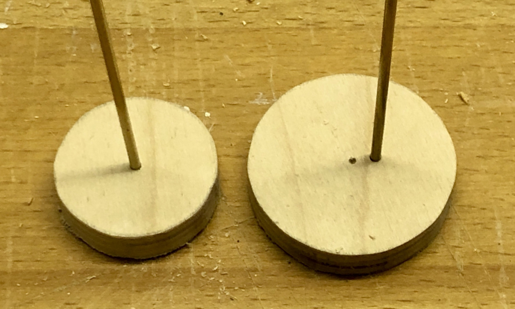
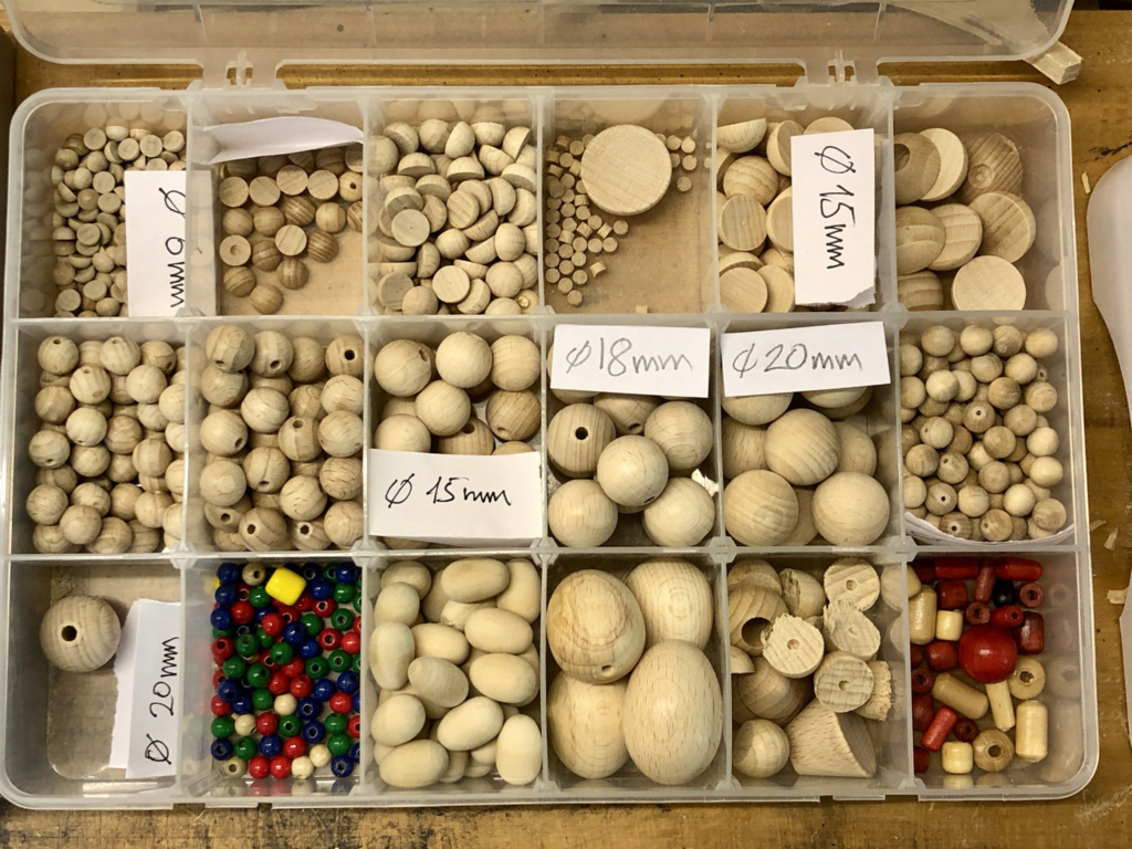
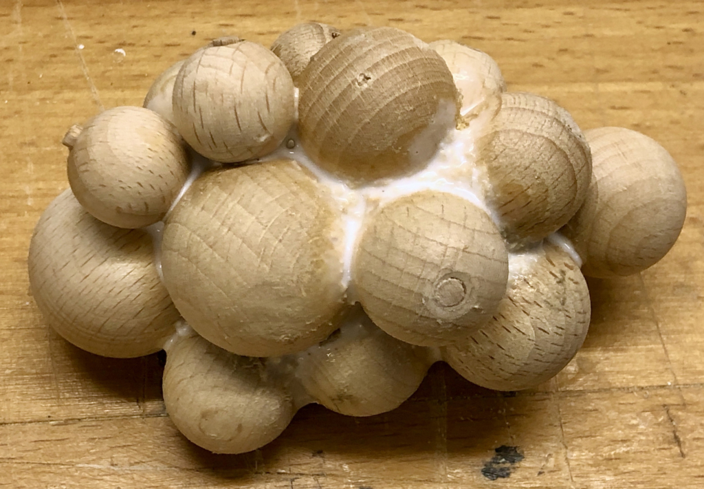
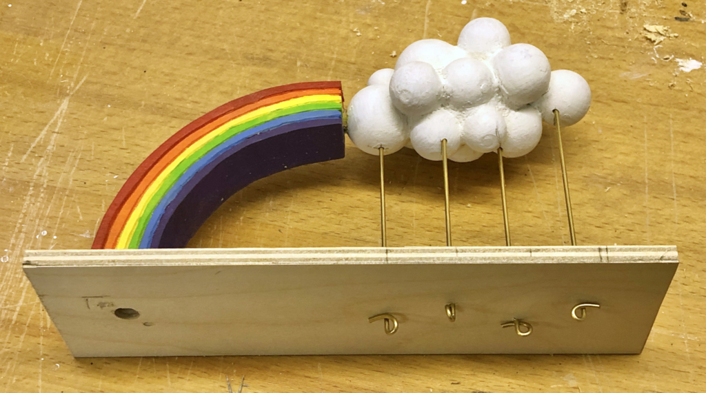
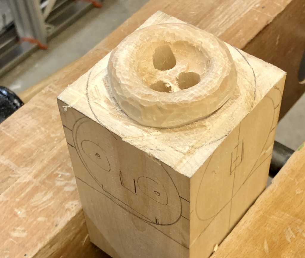
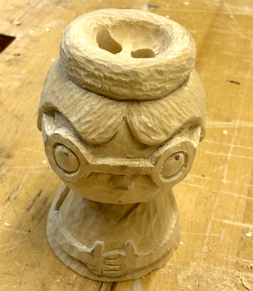
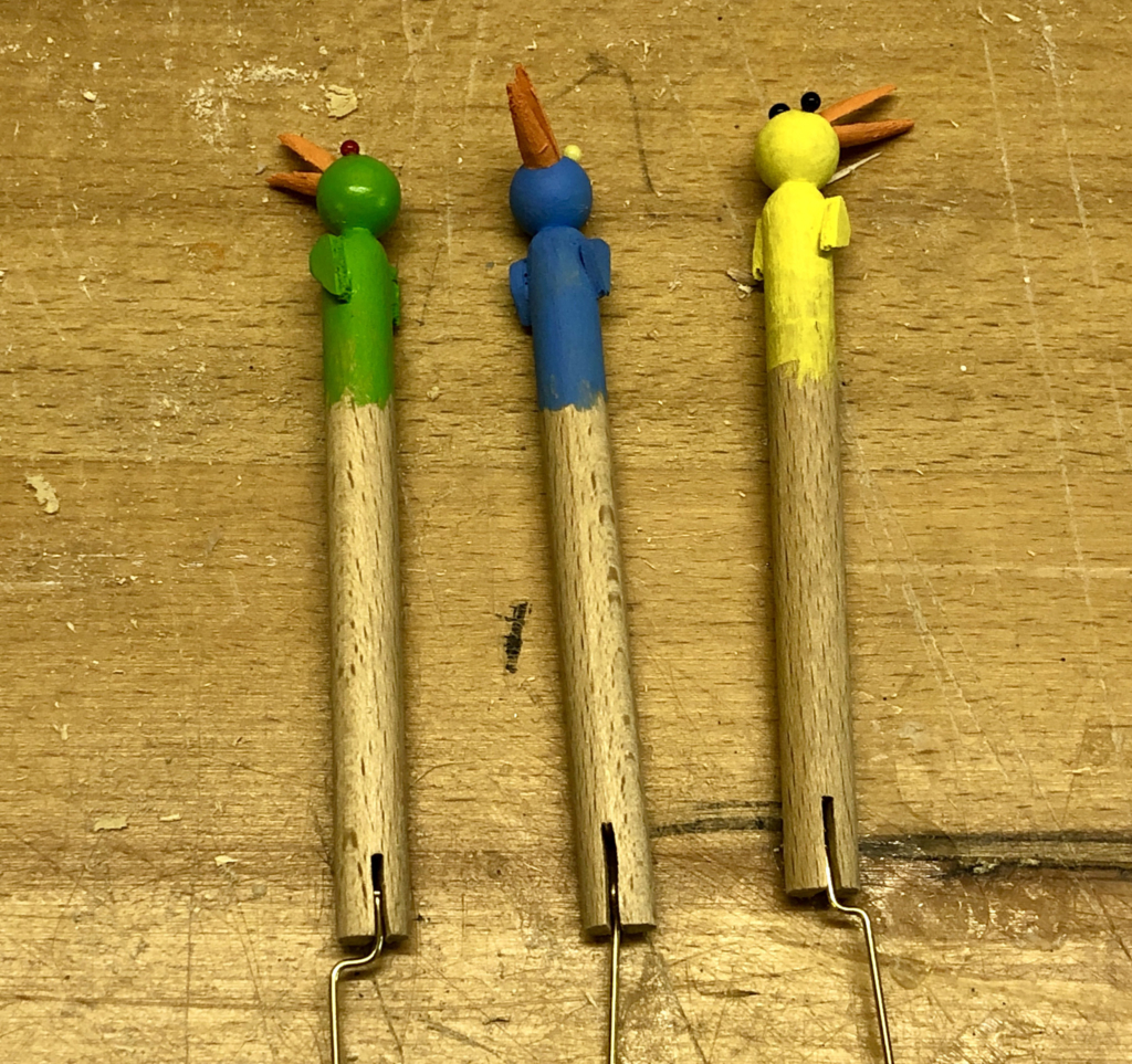
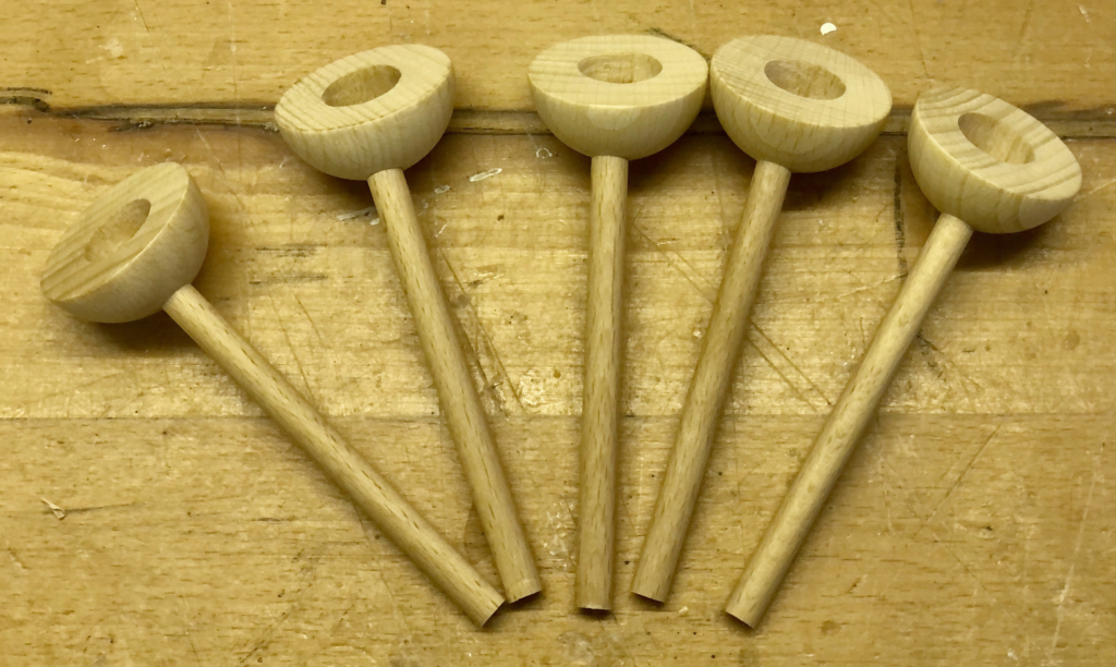
After fruitlessly trying just pieces of string, to see if they moved as I expected real hair to move, I decided that I had to add 5 mm wooden beads. Beaded strands with a length of 60 mm felt about right, falling vertically down at rest while swinging satisfyingly about when in motion. A wooden ring provided a good frame to glue the strands to a wooden hemisphere. Some 5 mm dowel allows the hair to be plugged in to the top of the head.
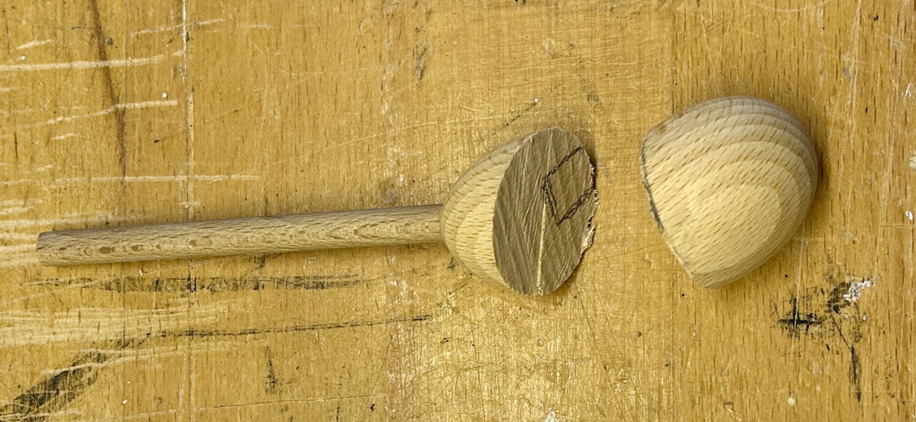
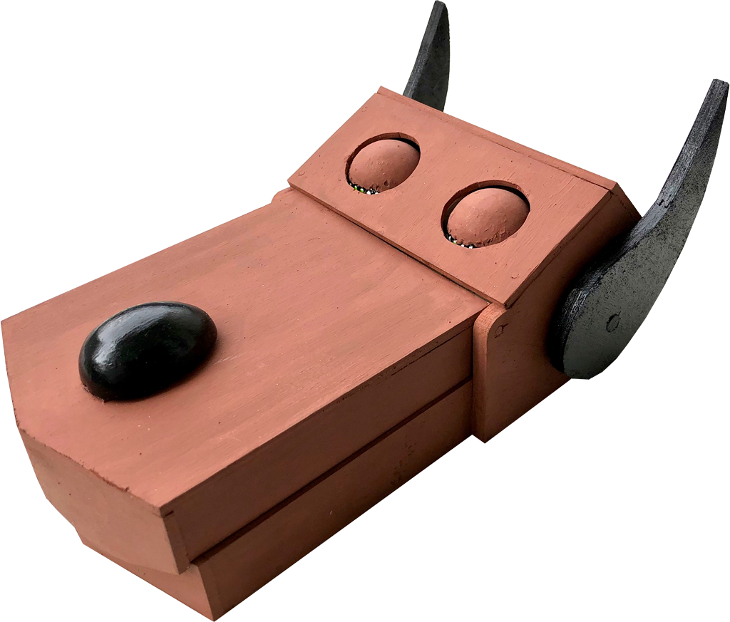
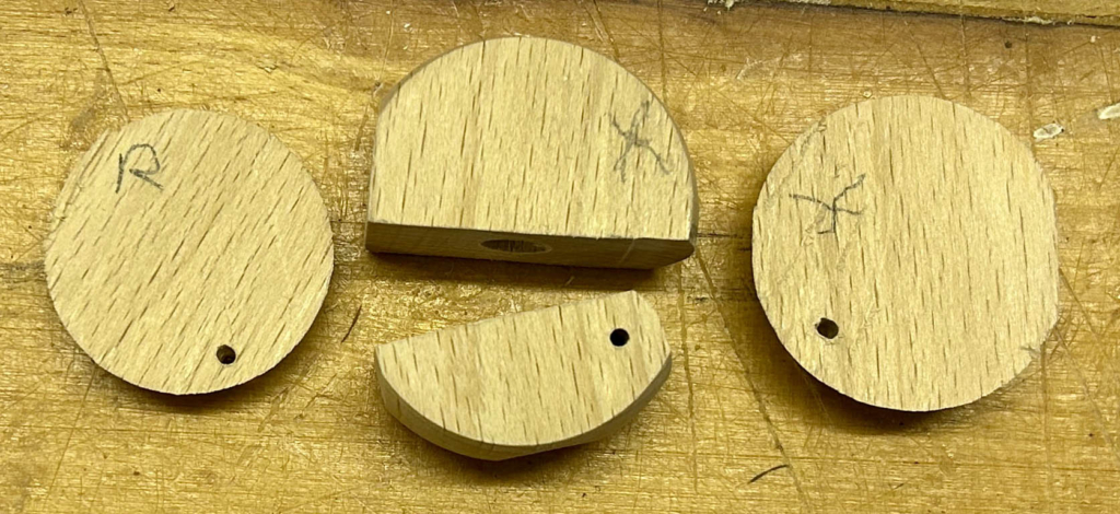
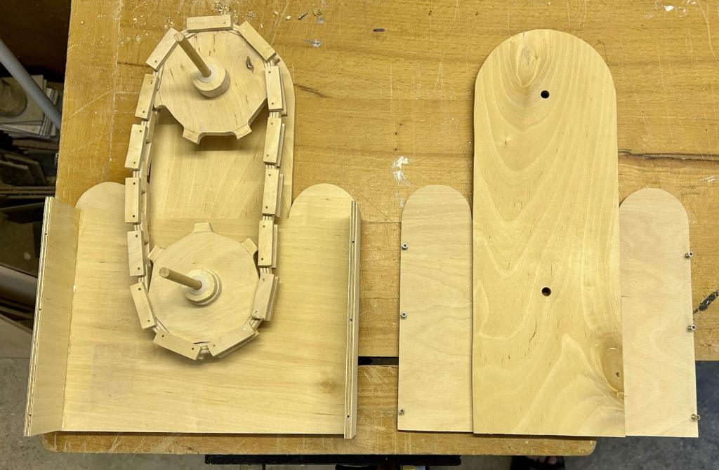
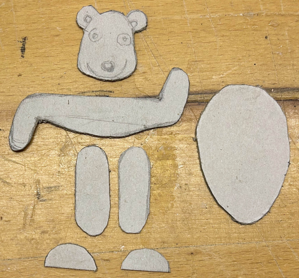
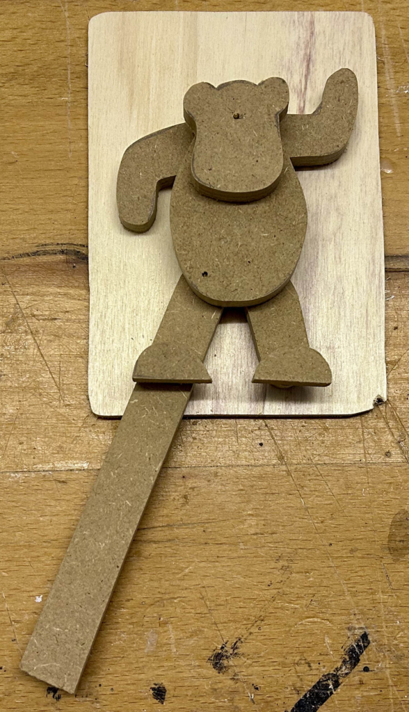
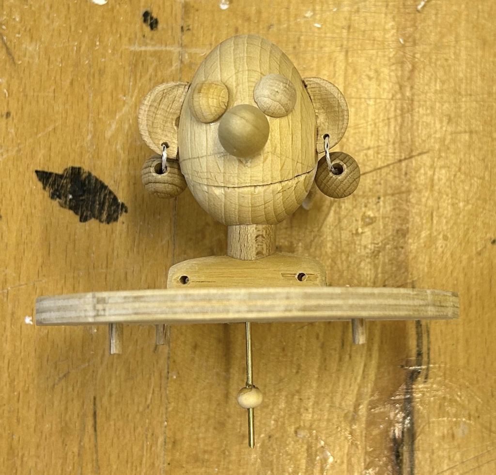
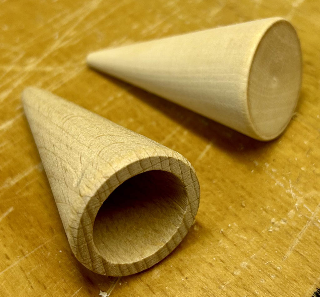
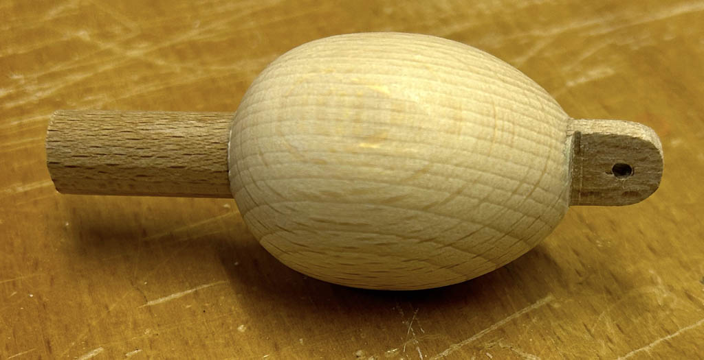
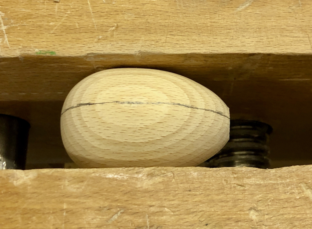
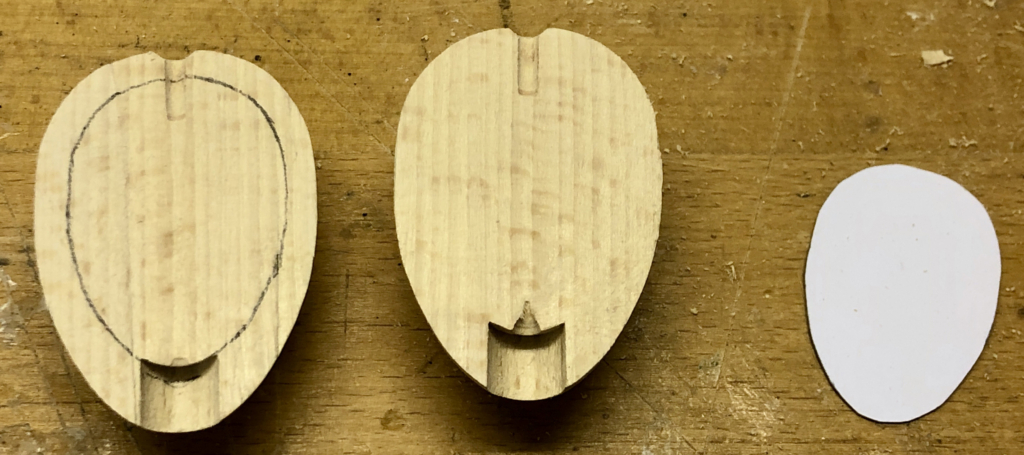
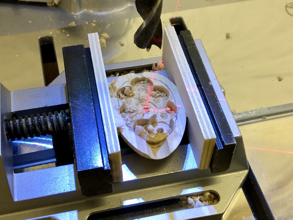
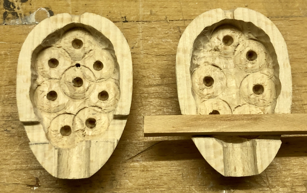
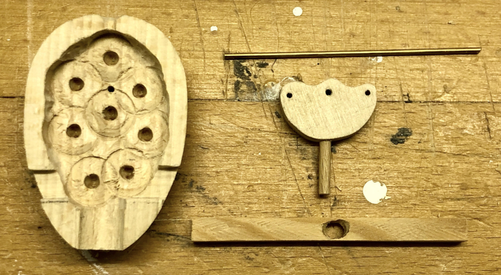
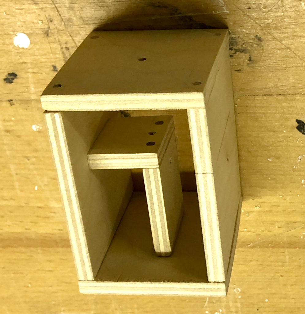
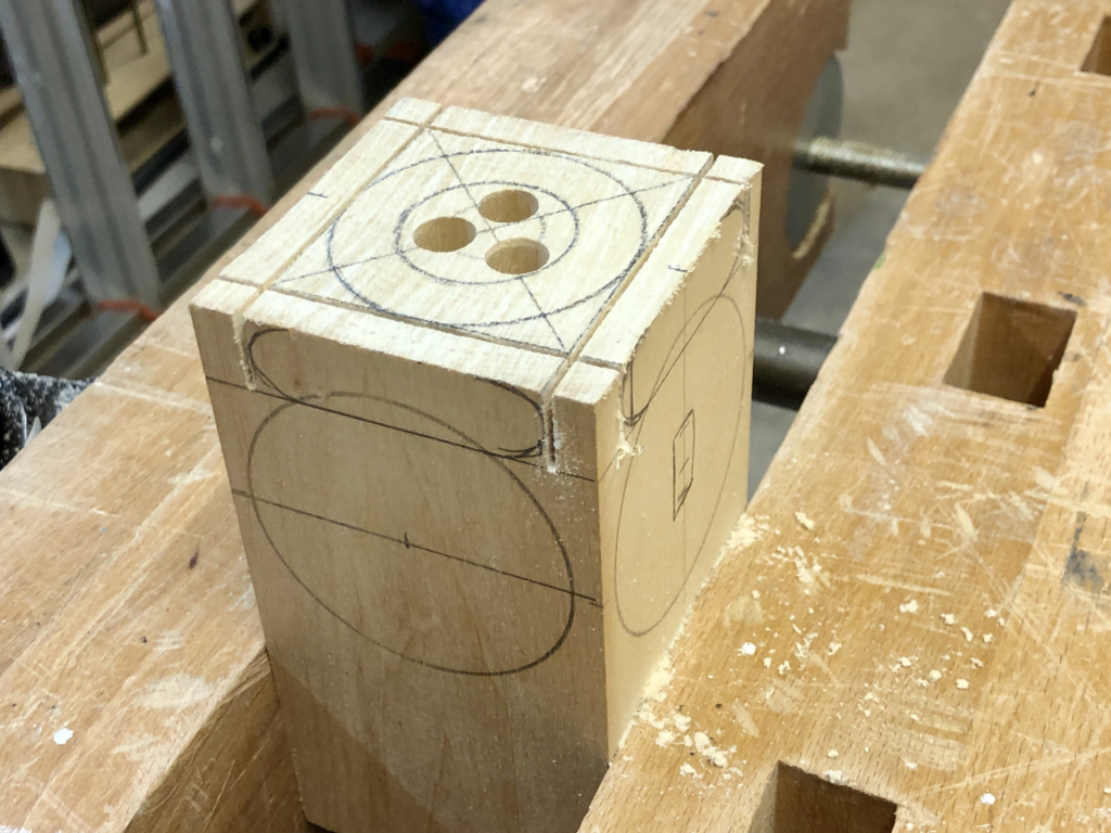
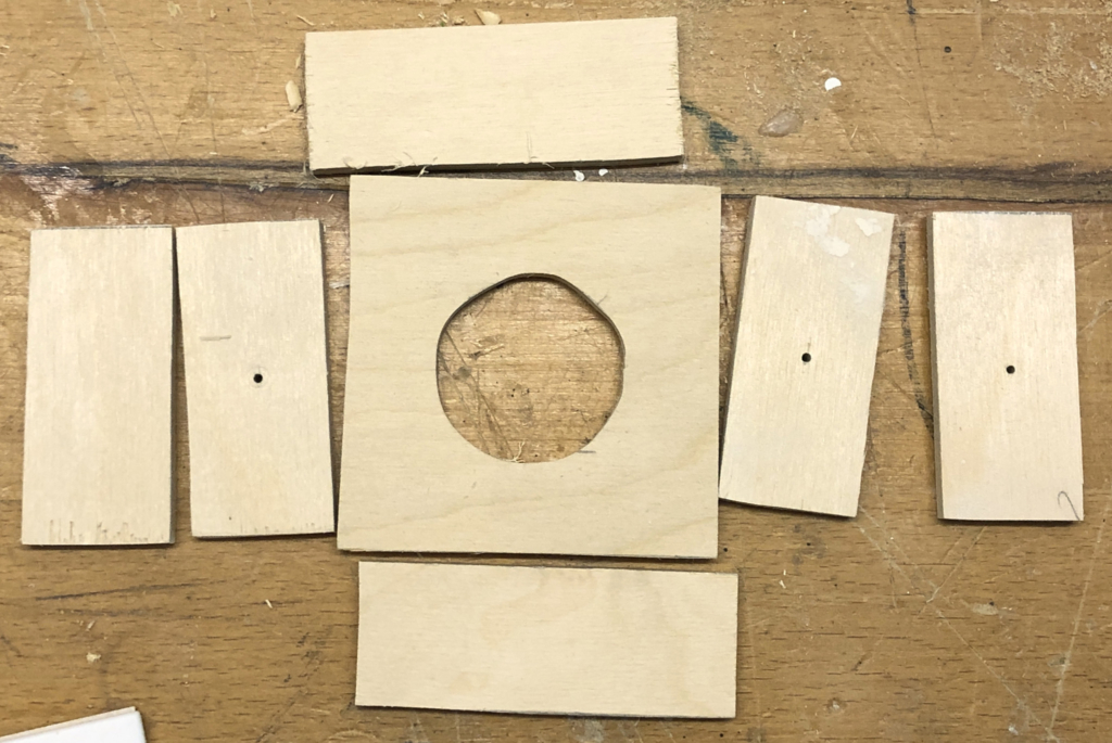
The Head
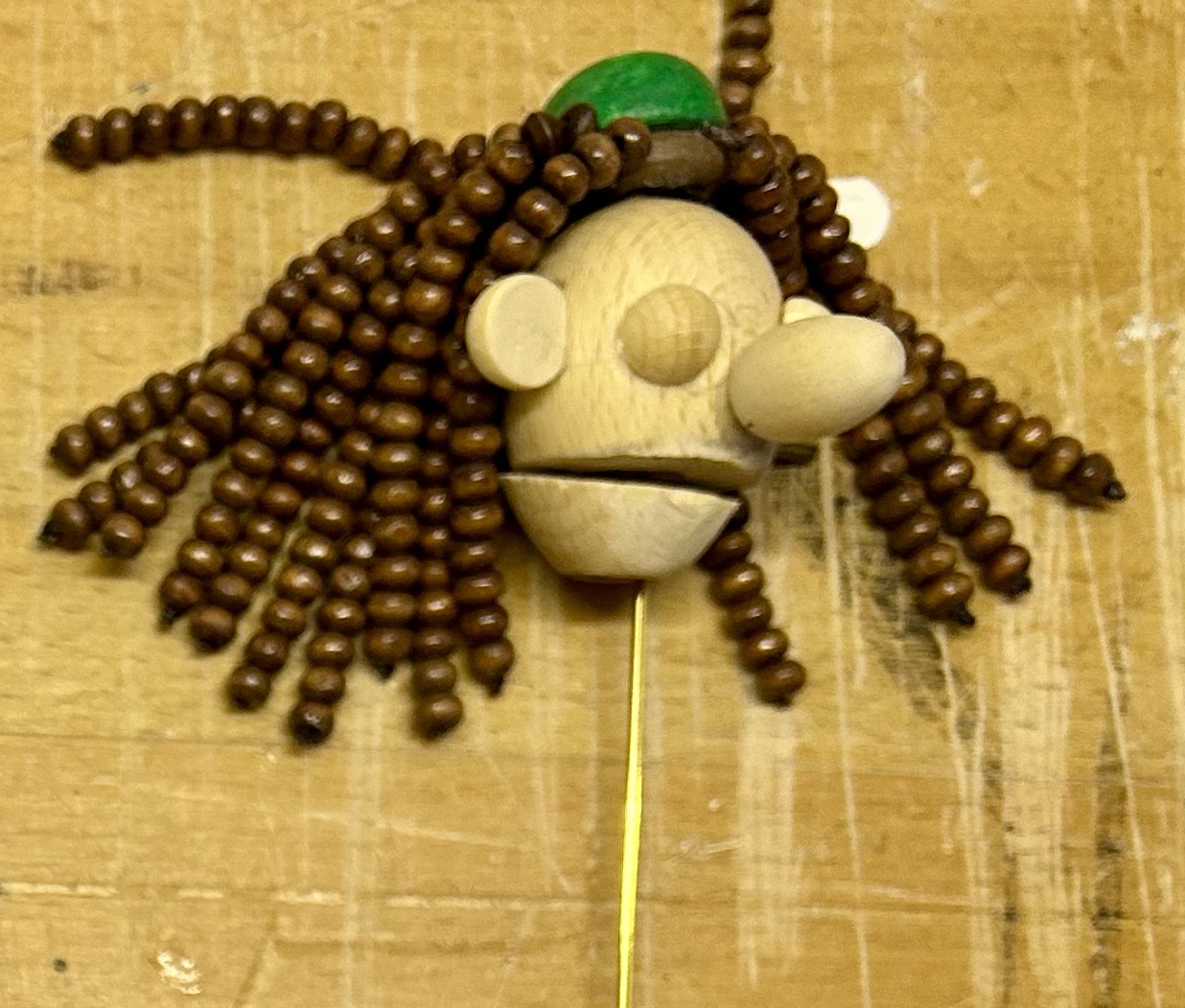
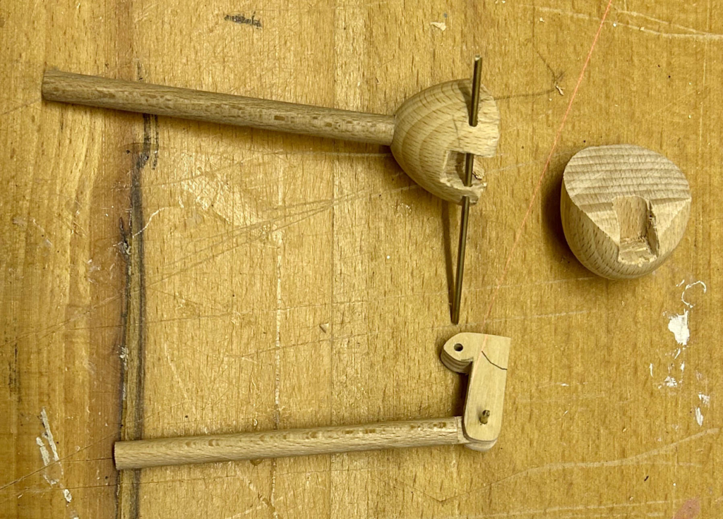
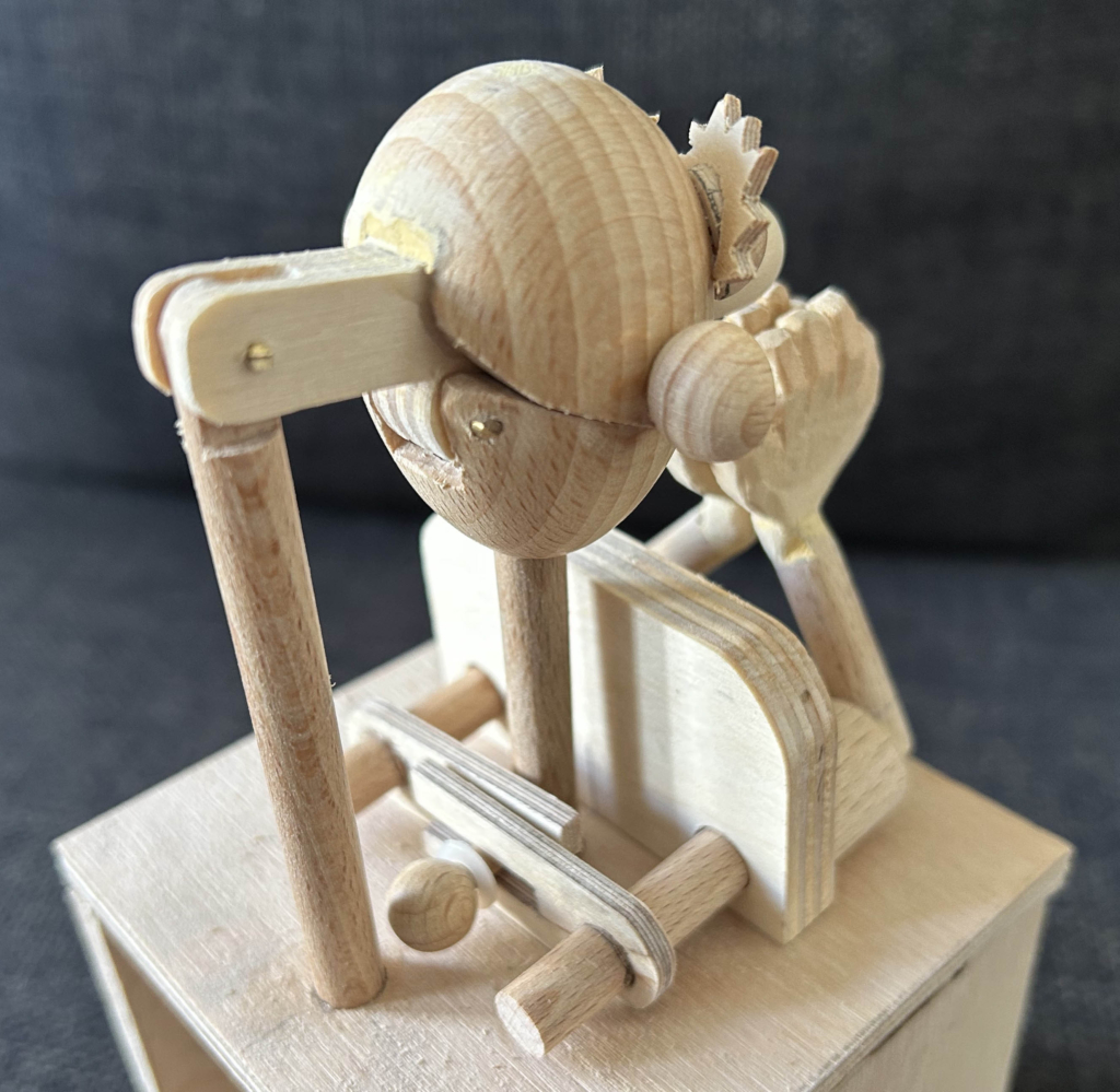
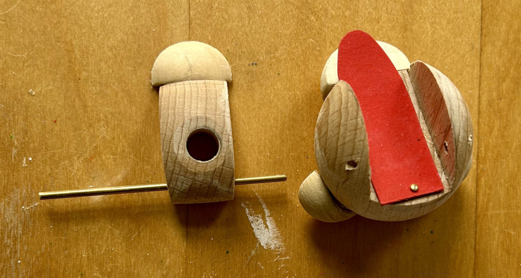
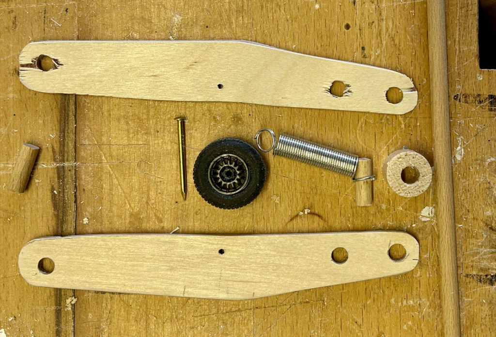
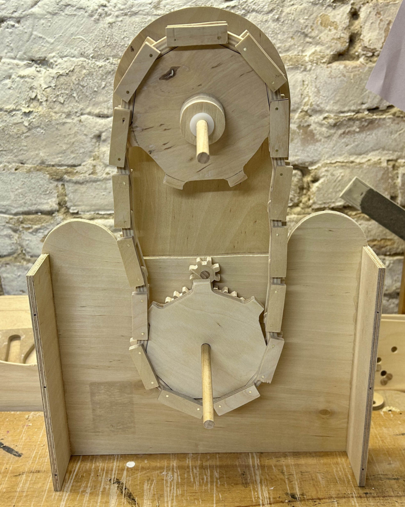
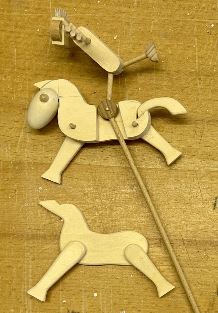
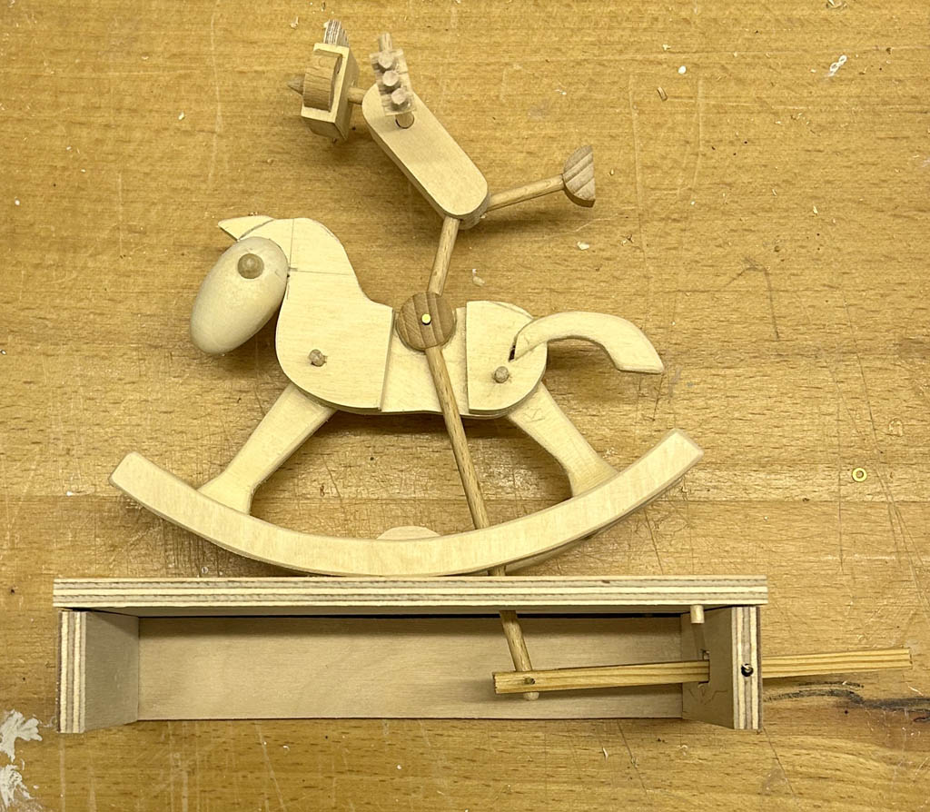
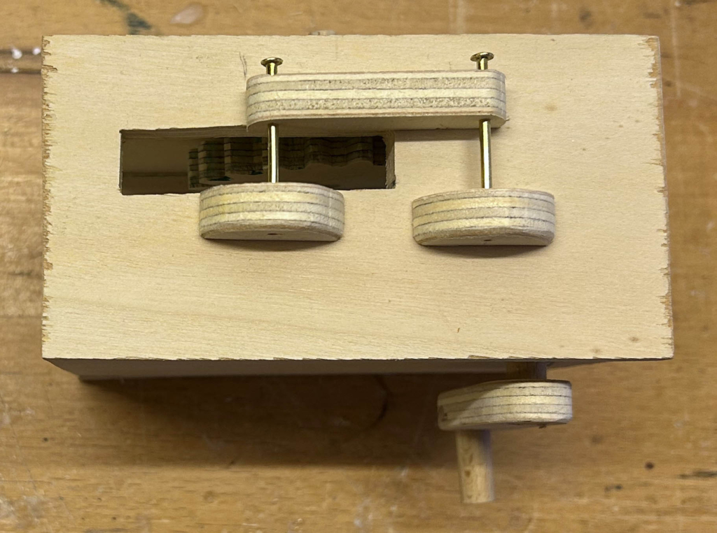
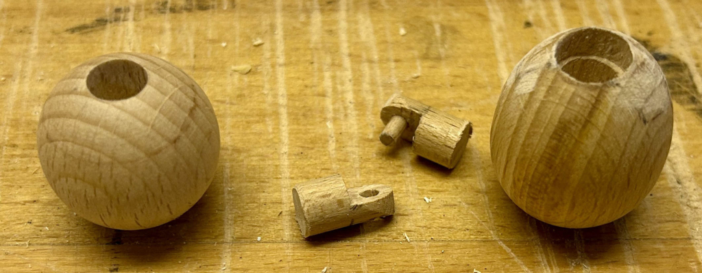
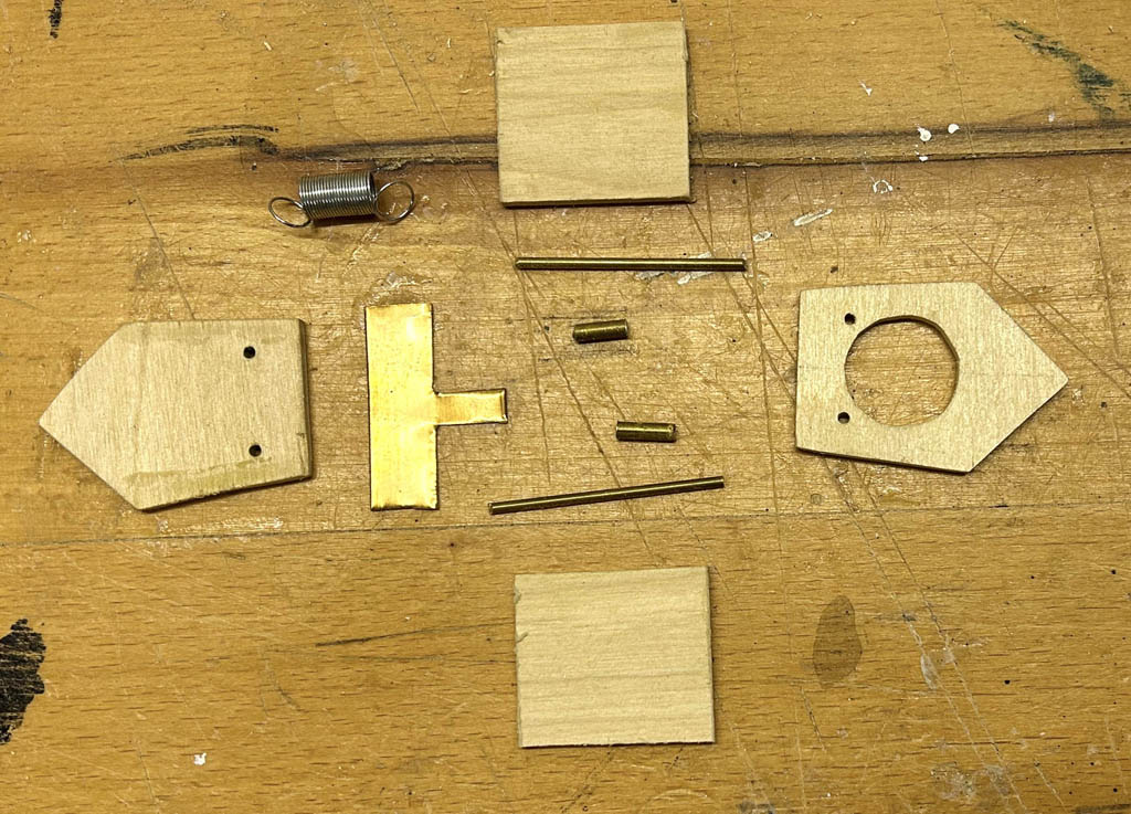
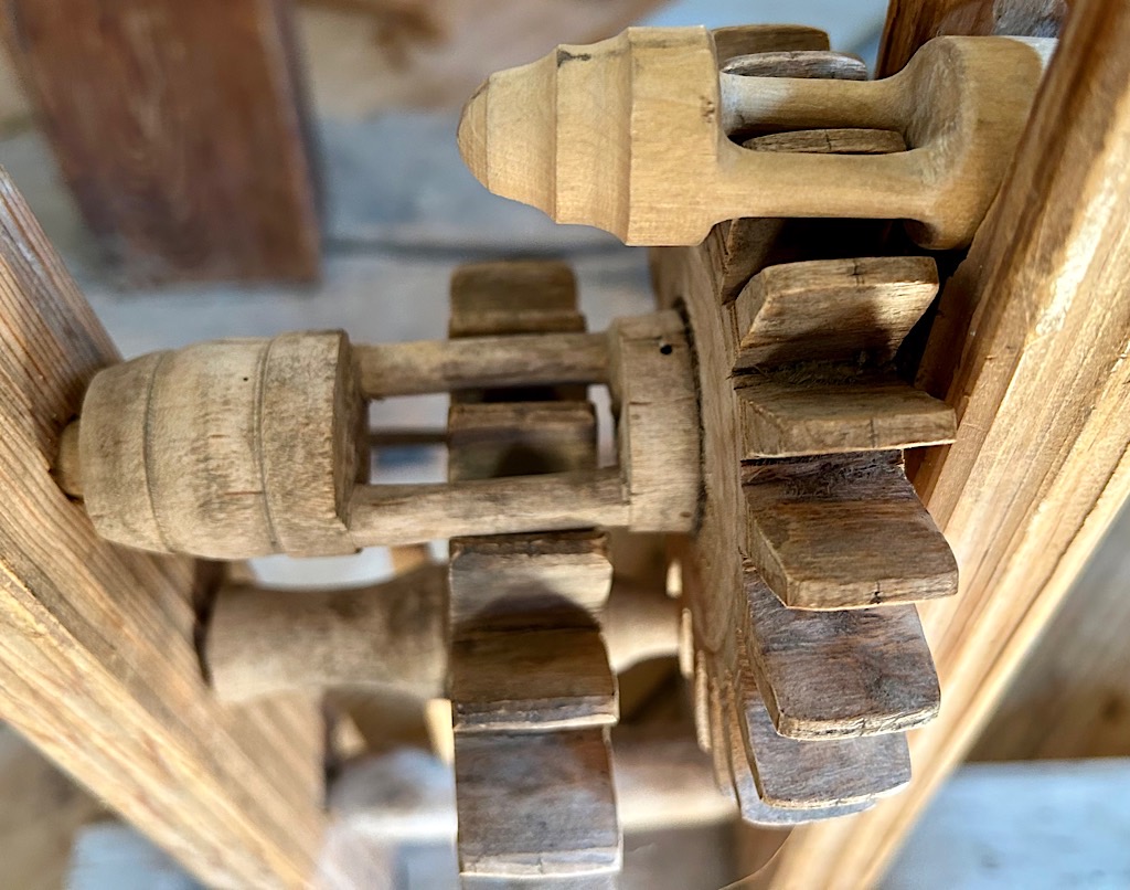
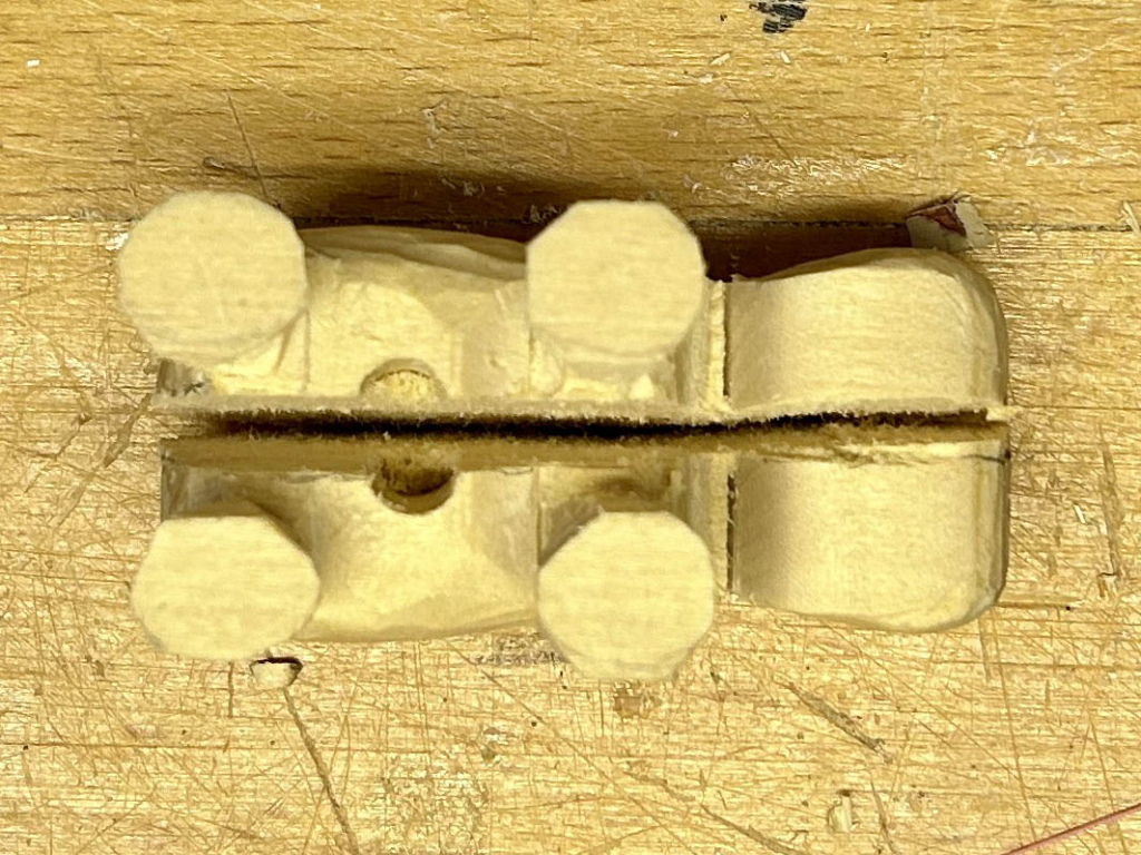
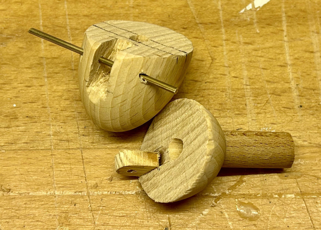
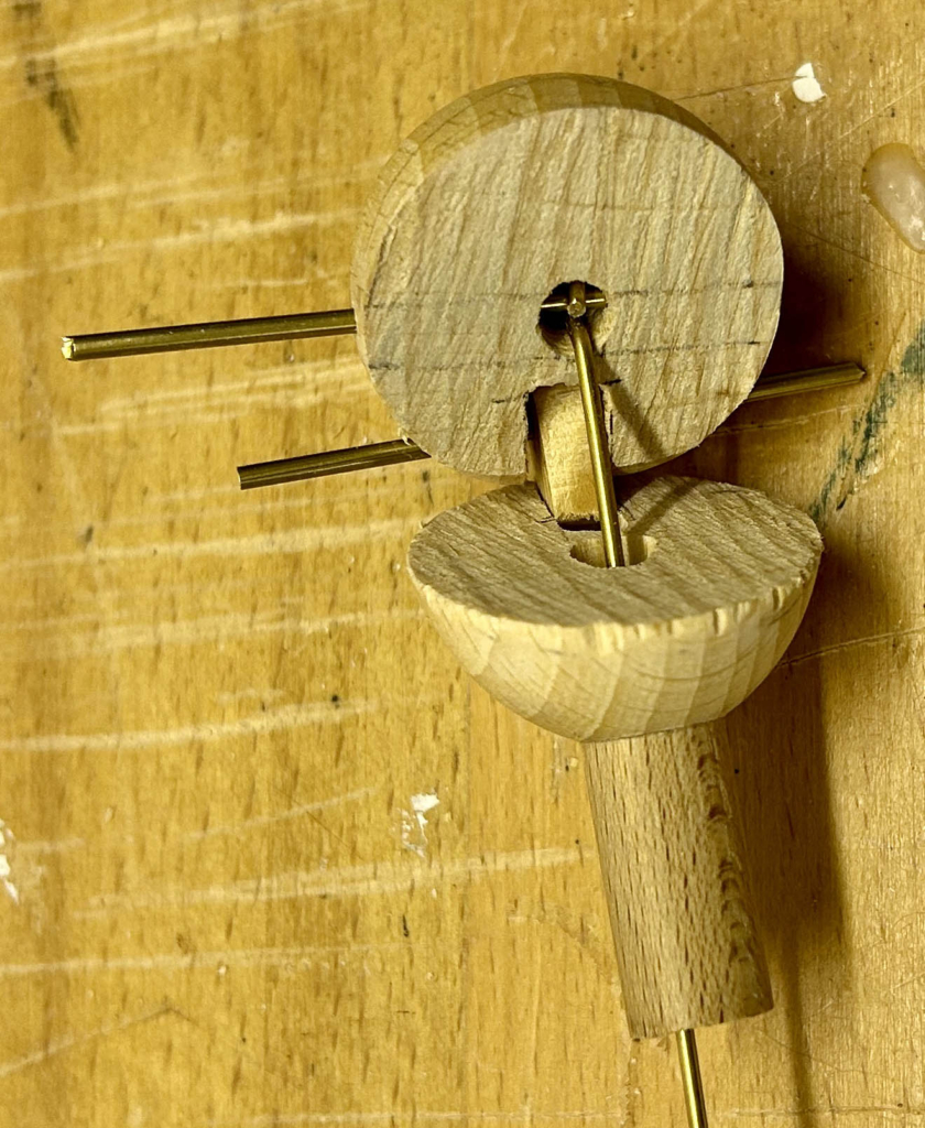
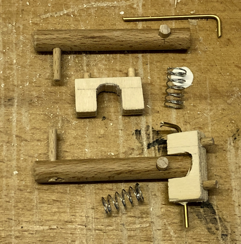
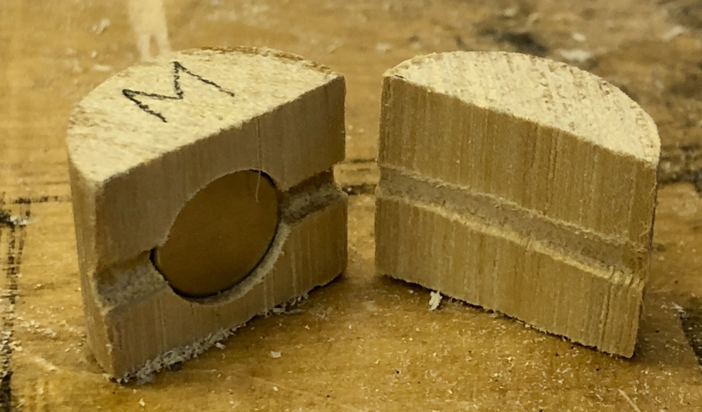
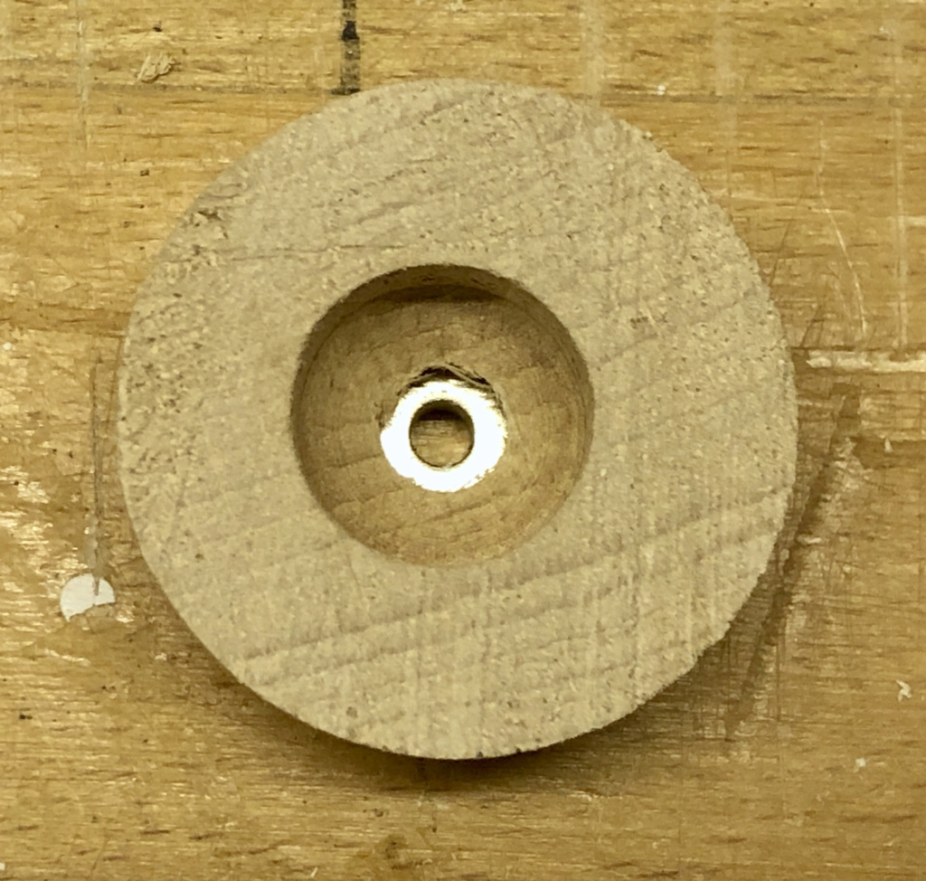
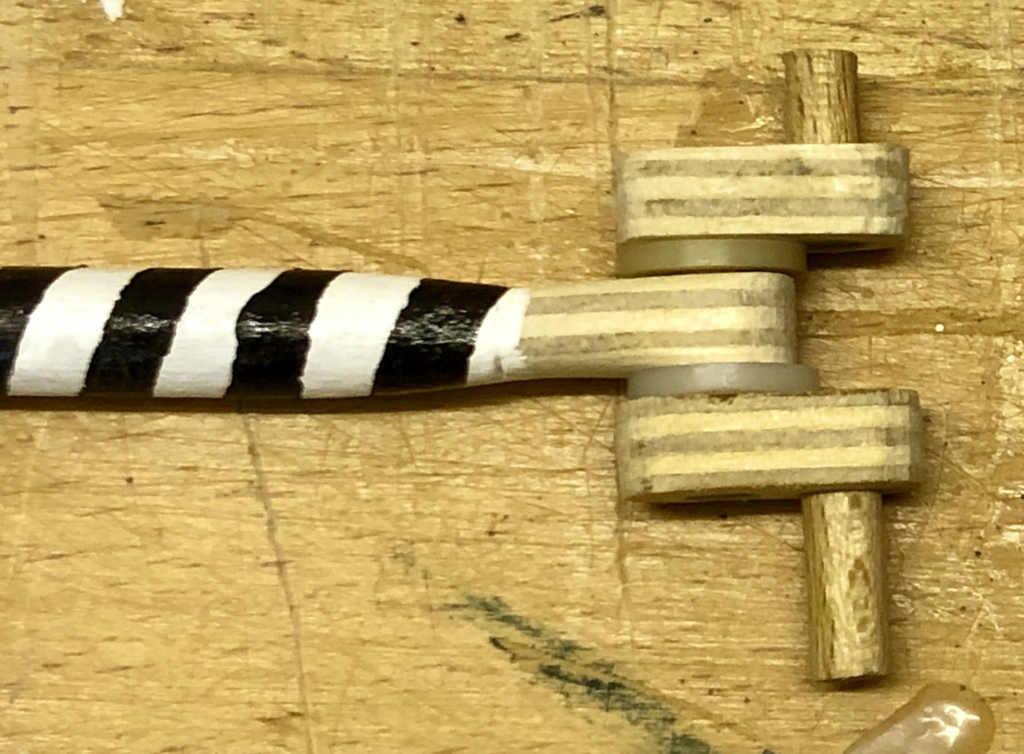
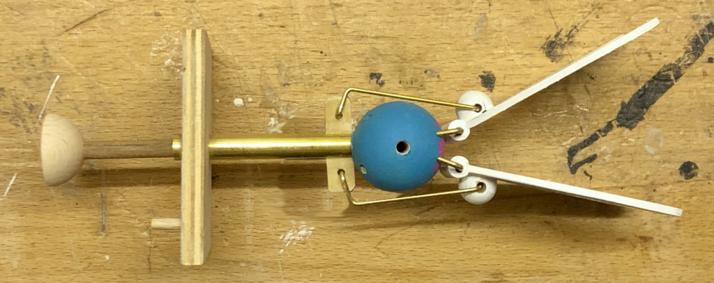
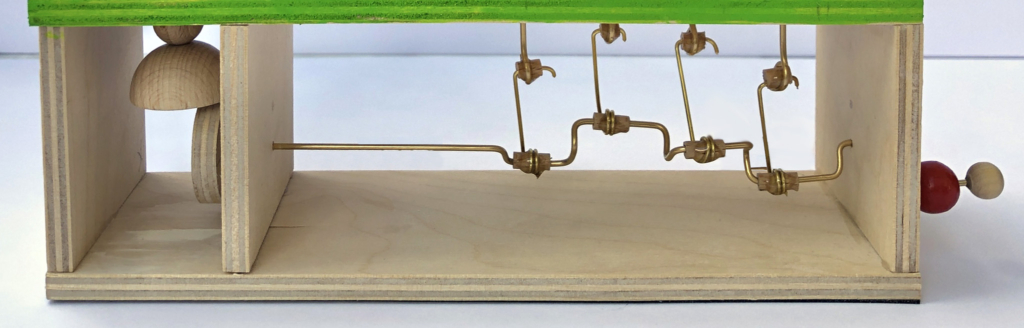
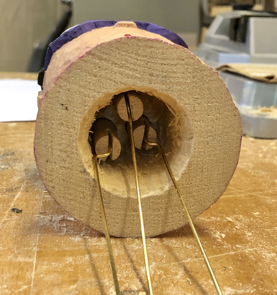
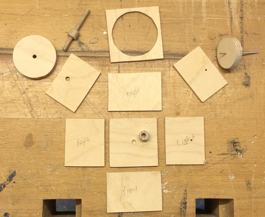
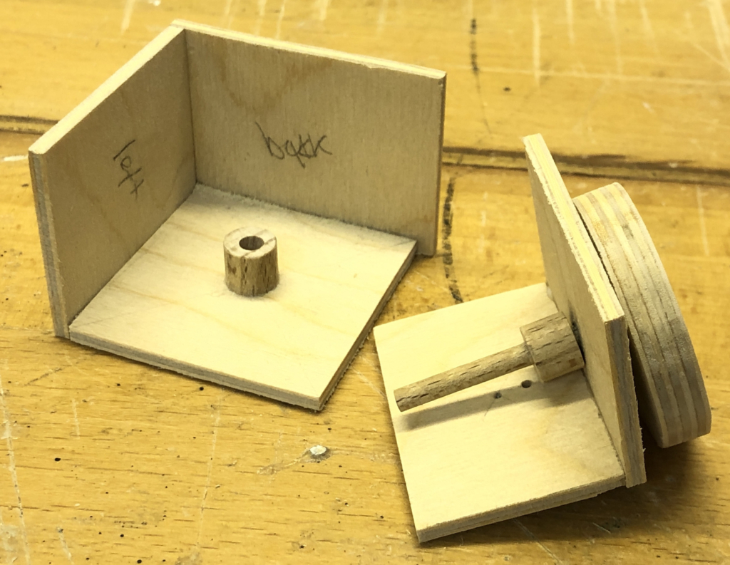
The jaw is hinged at the back of the head and has a 10 mm hole to fit onto the hollow neck.
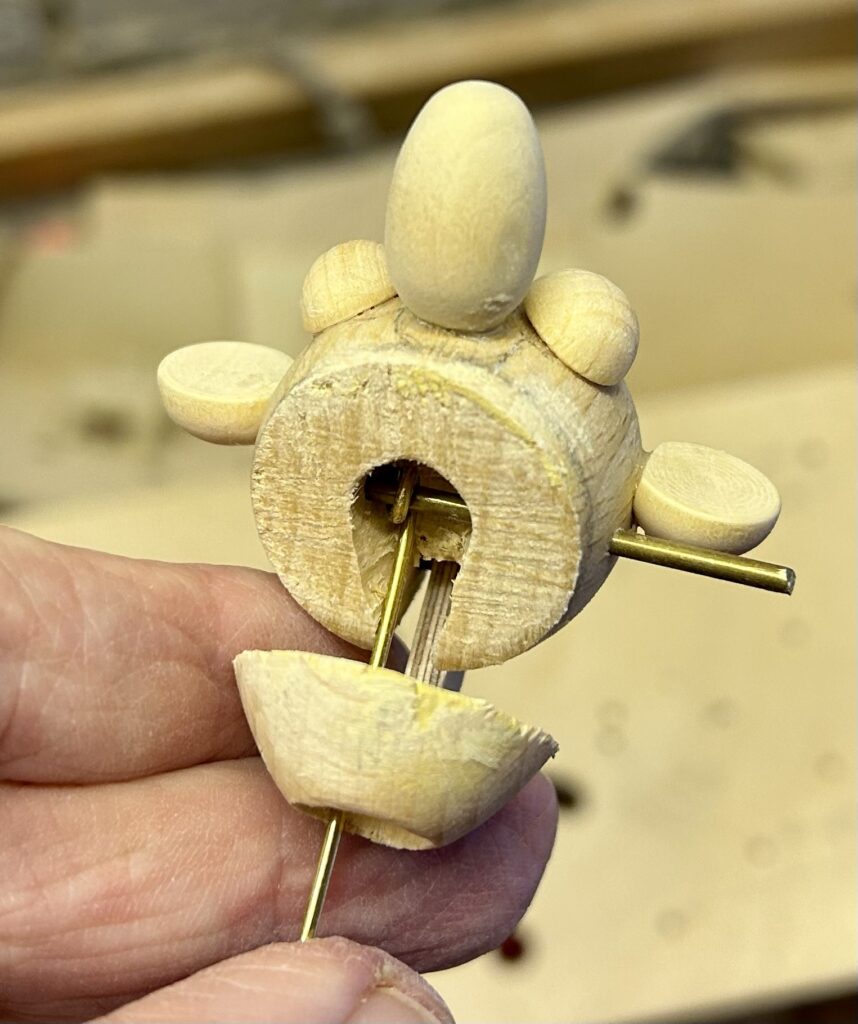
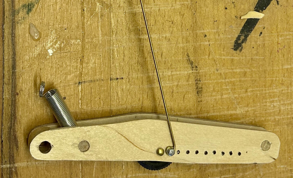
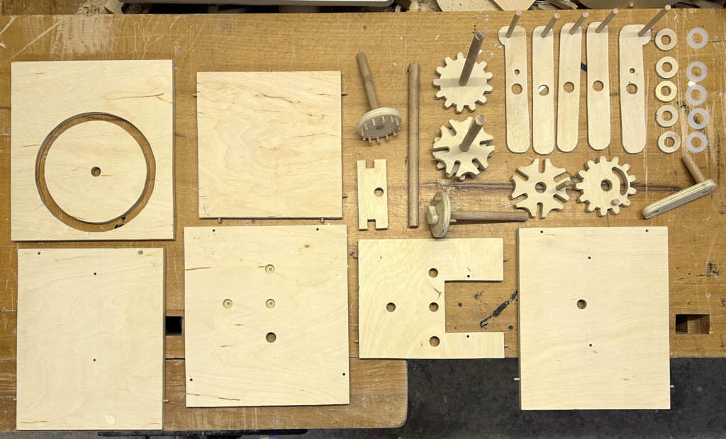
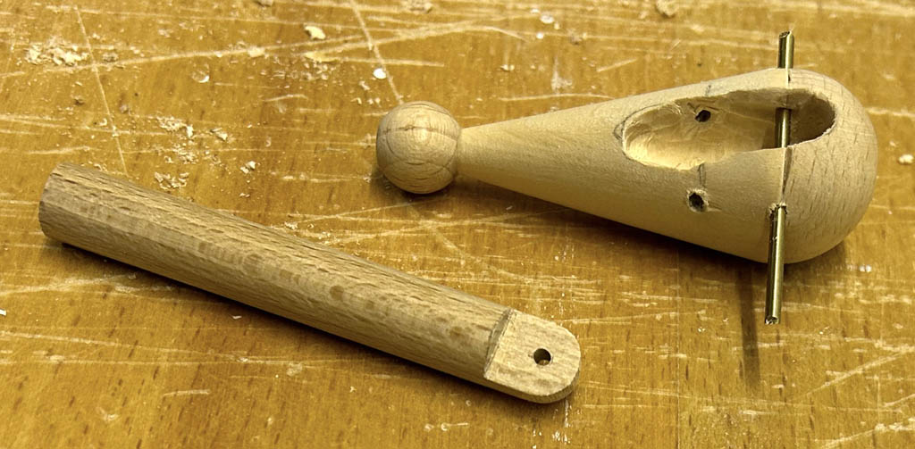
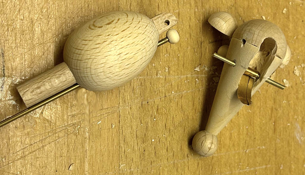
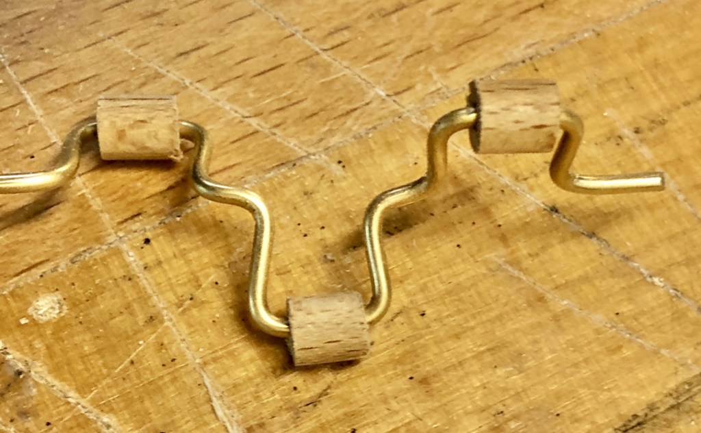
The brass rod to open the mouth hinges on a horizontal rod in the head. Pushing the rod up opens the mouth, pulling it down closes the mouth.
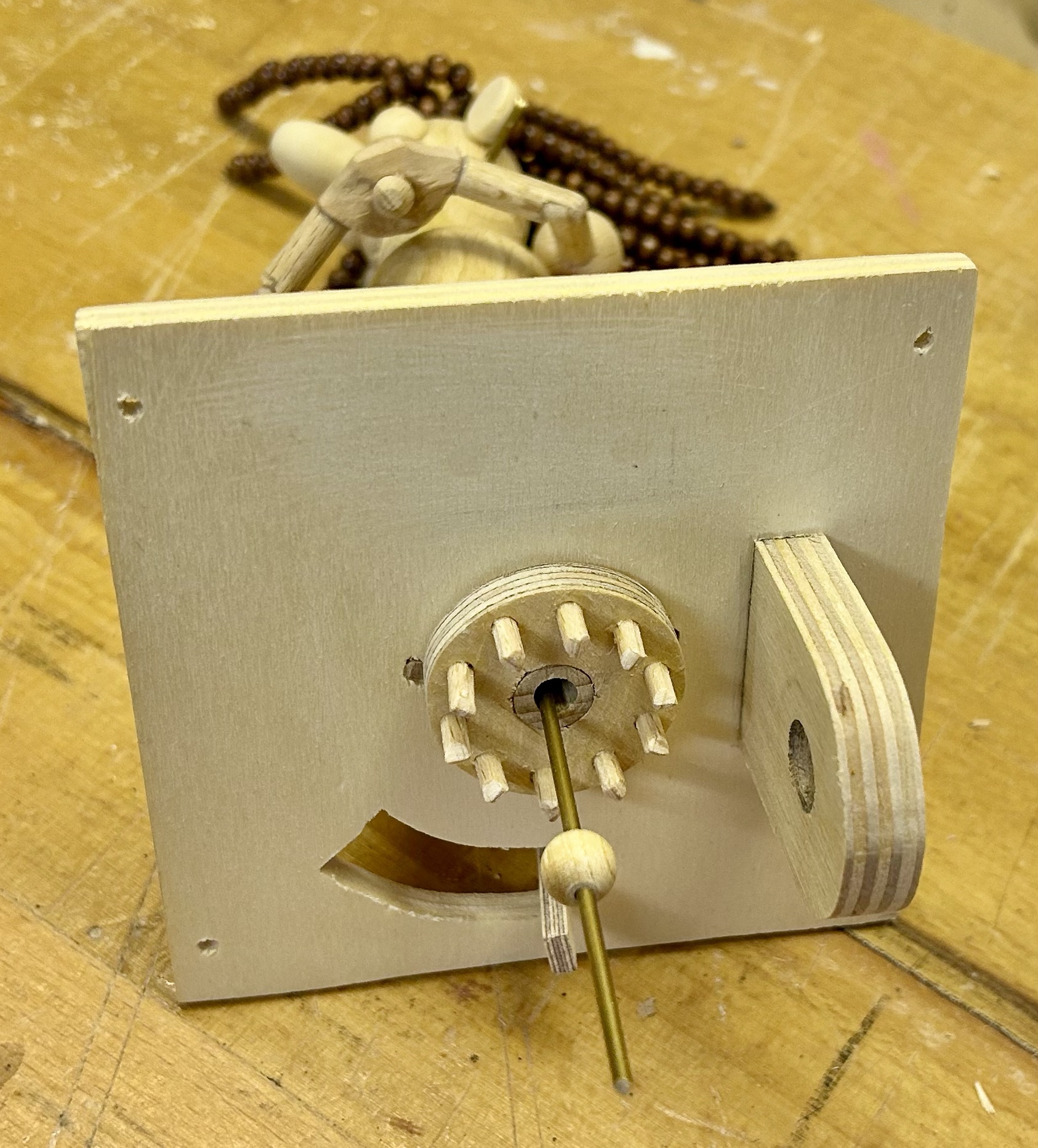
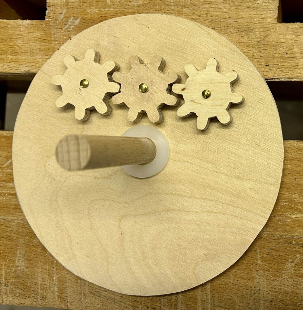
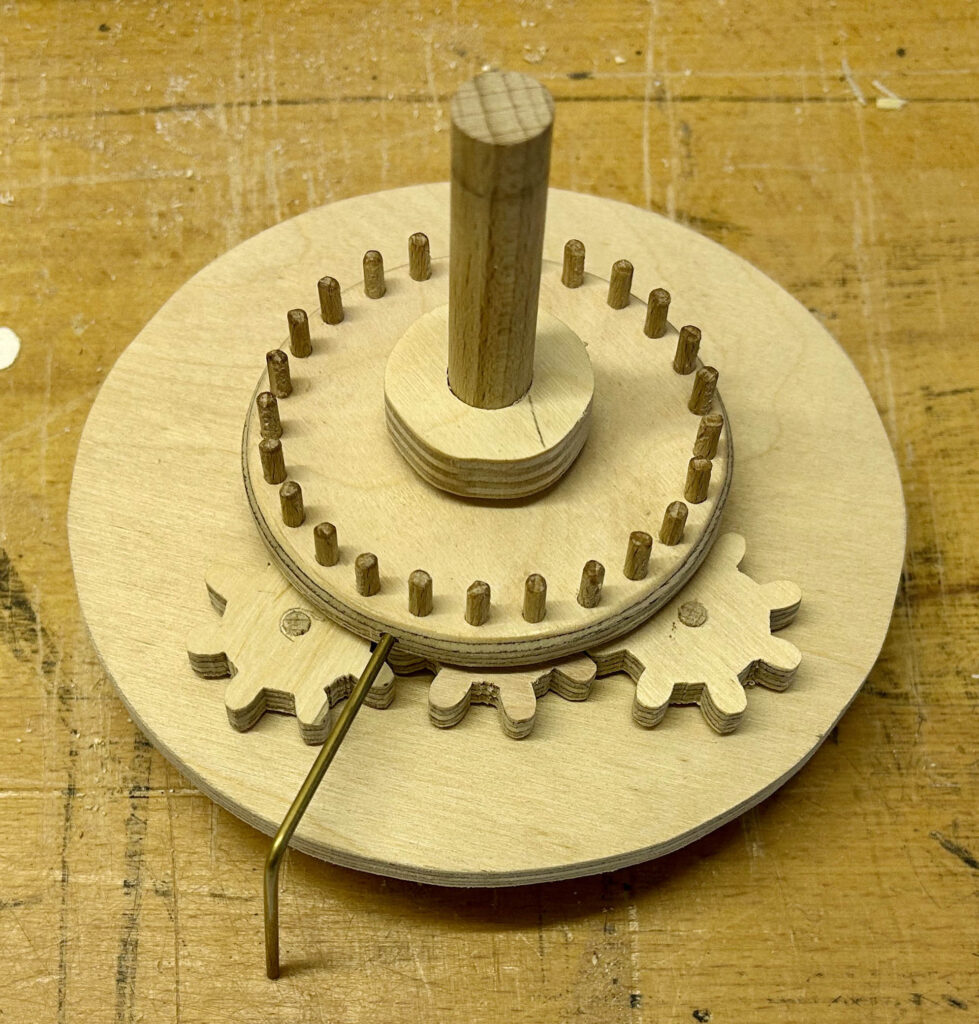
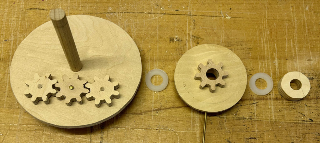
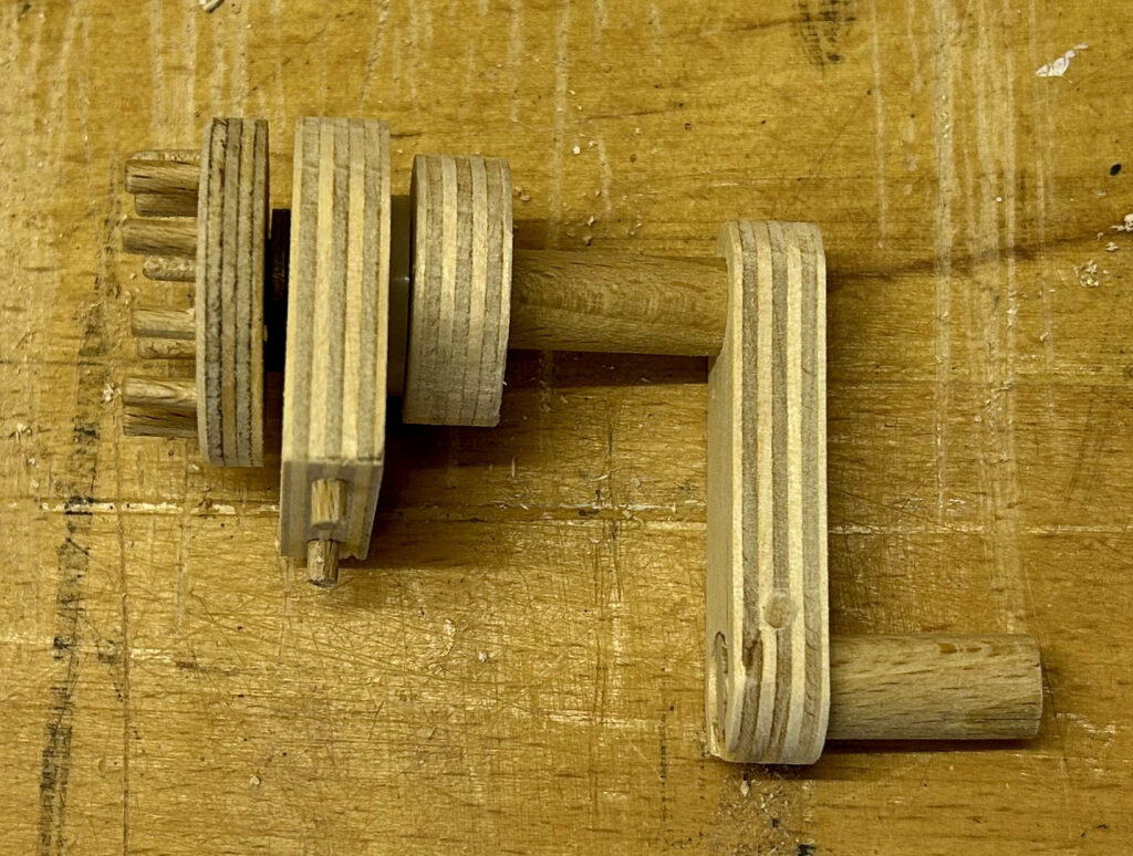
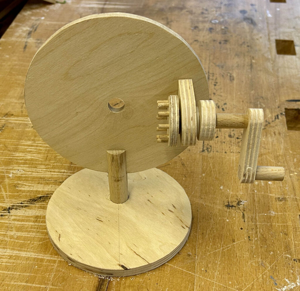
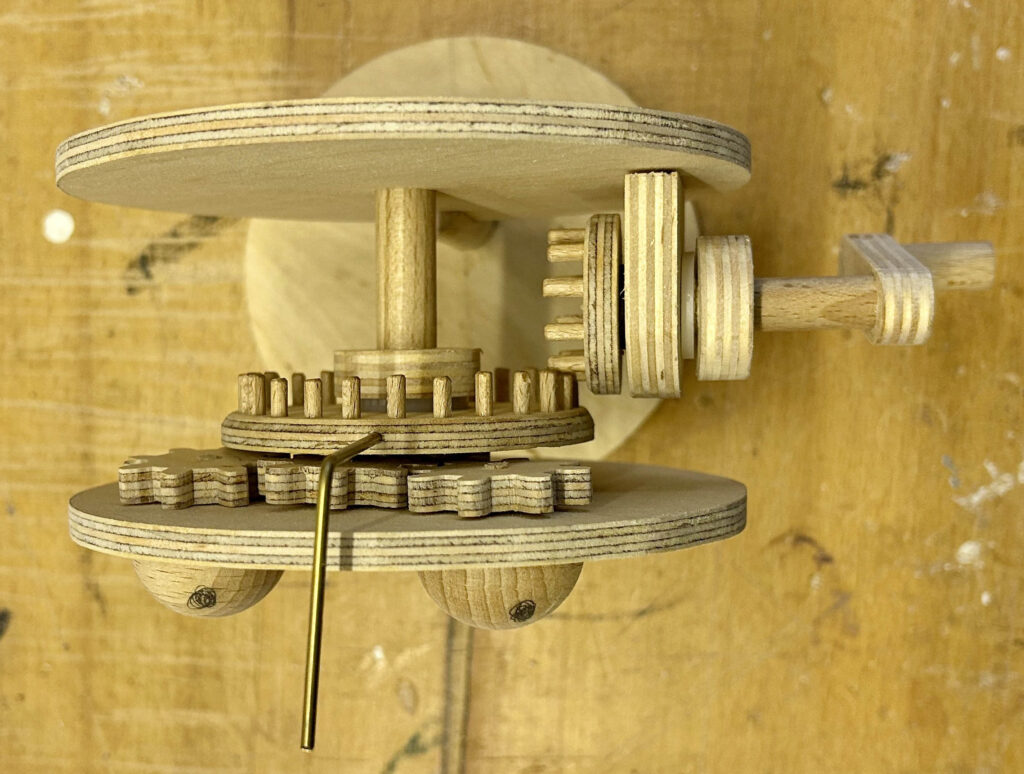
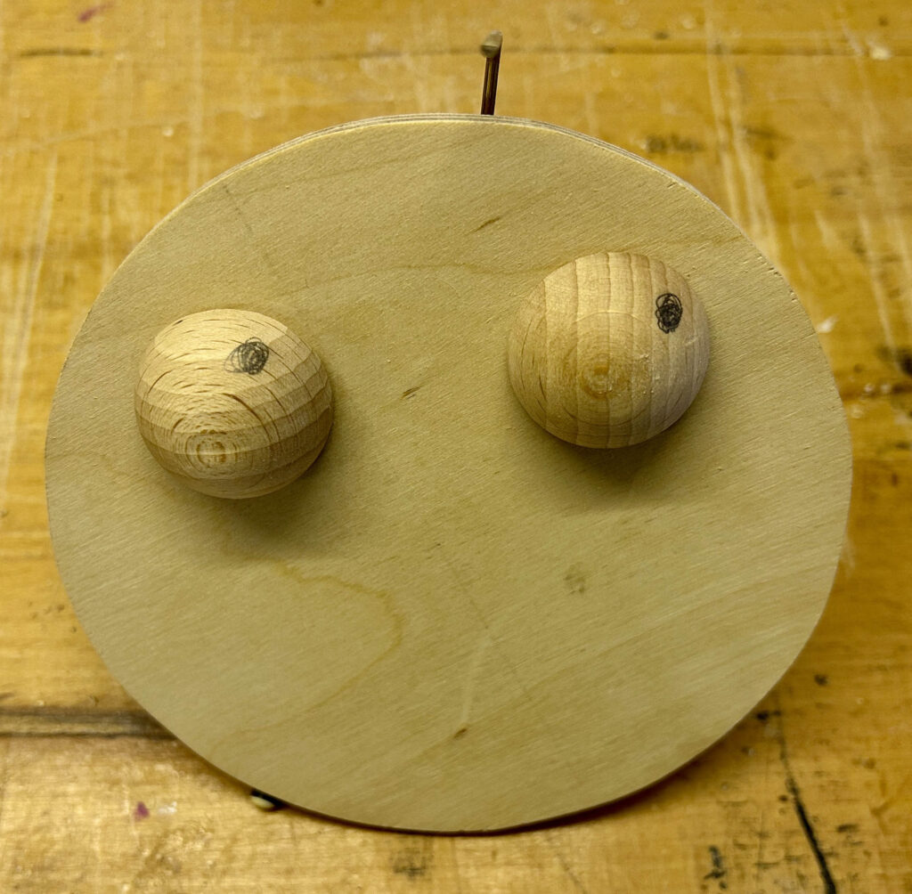
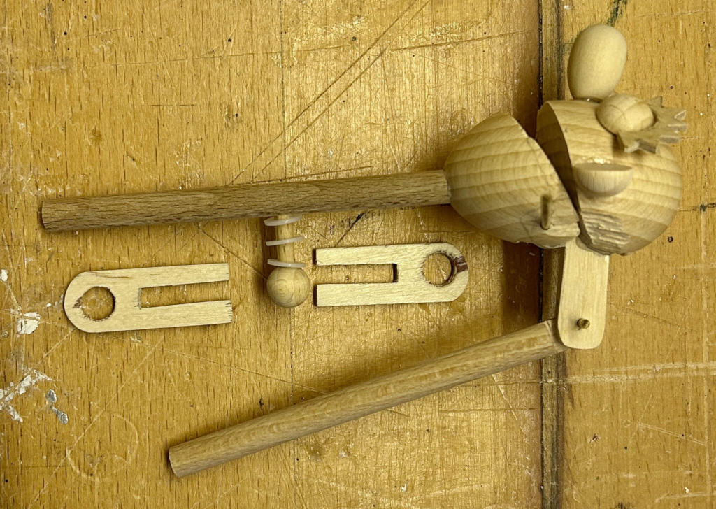
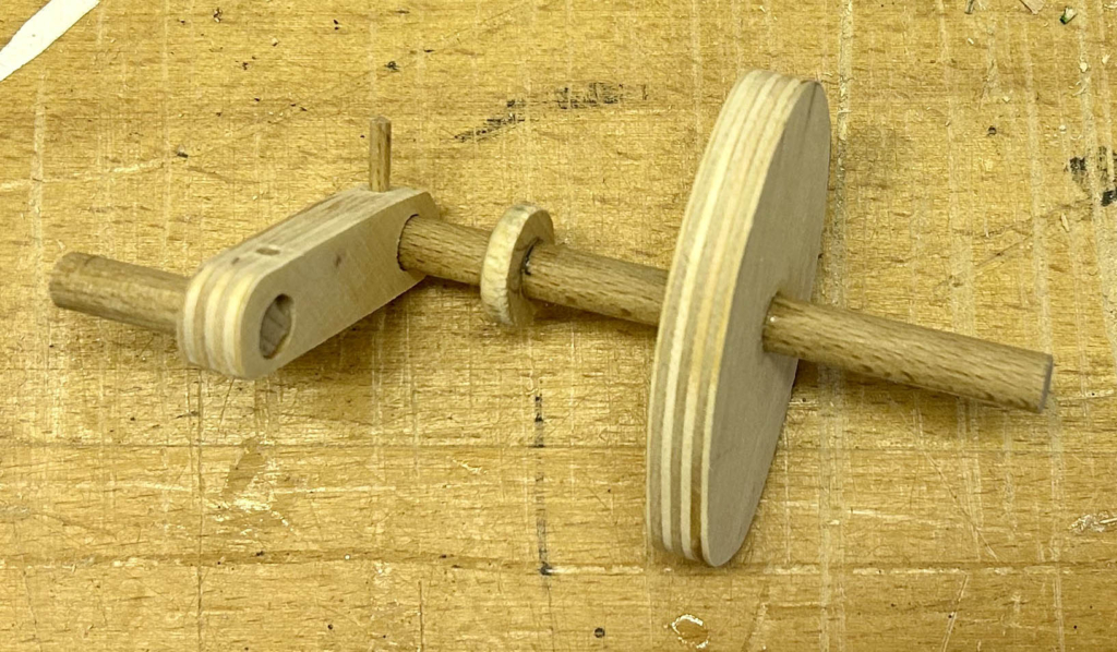
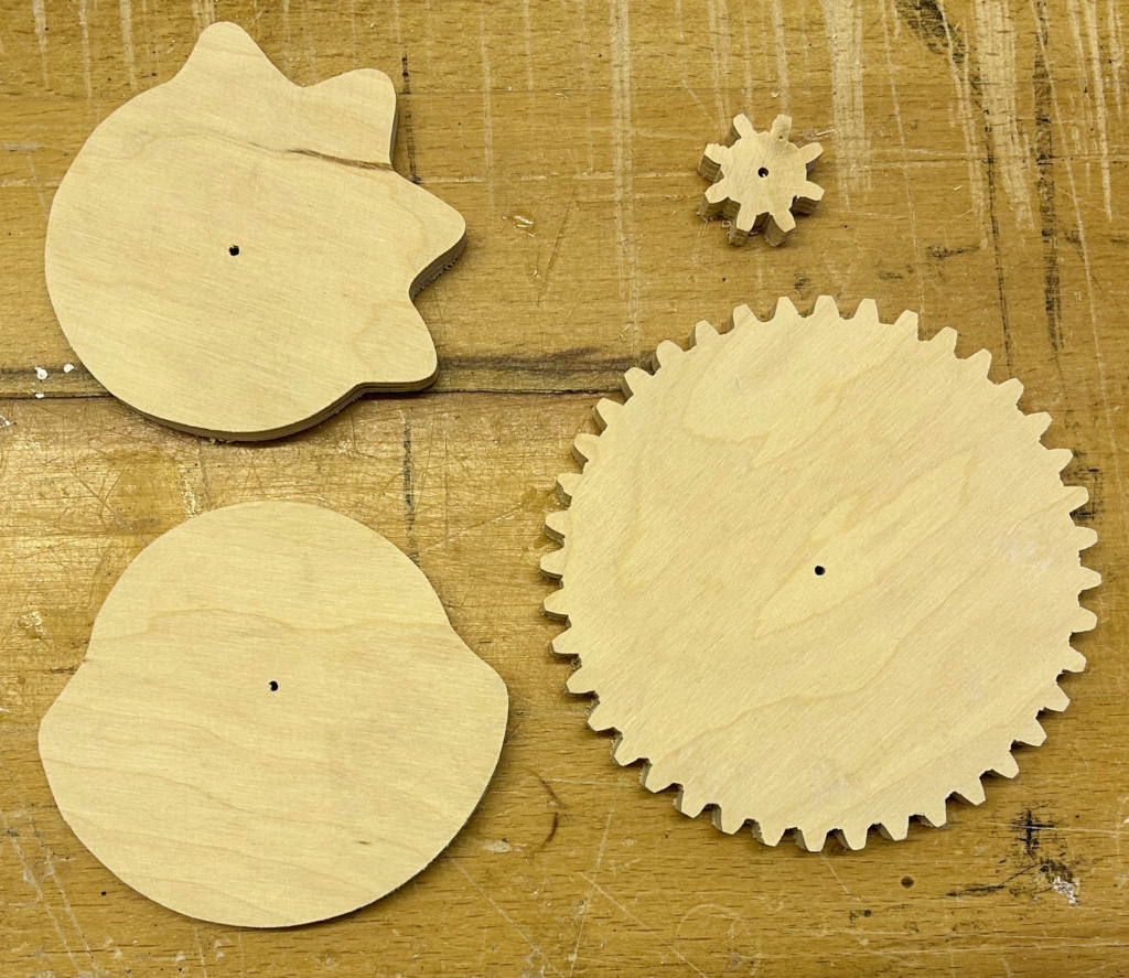
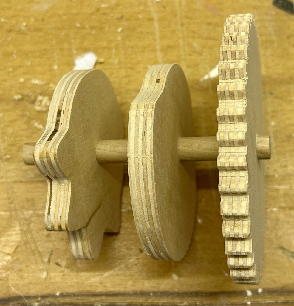
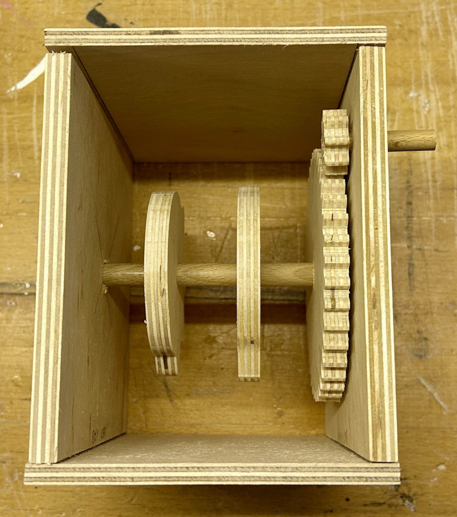
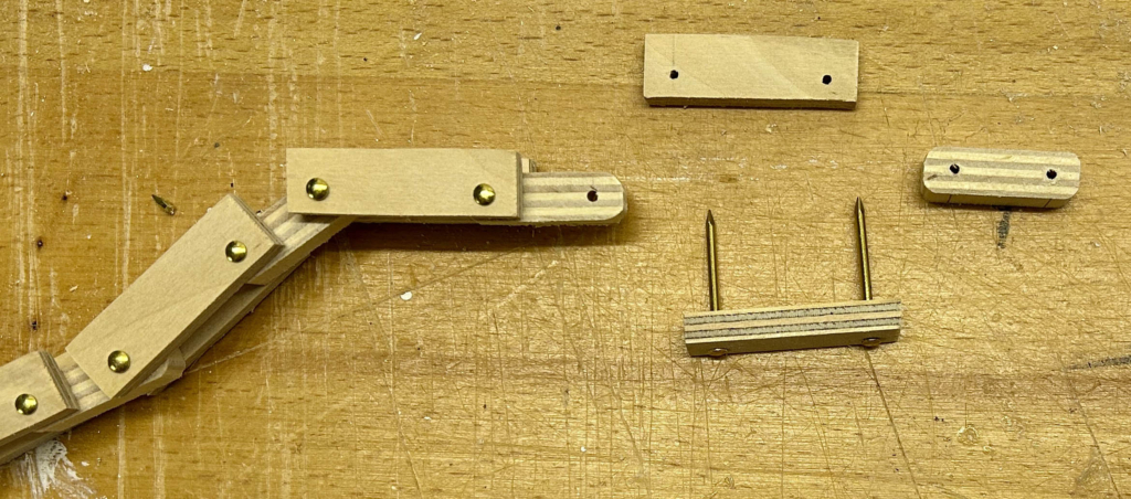
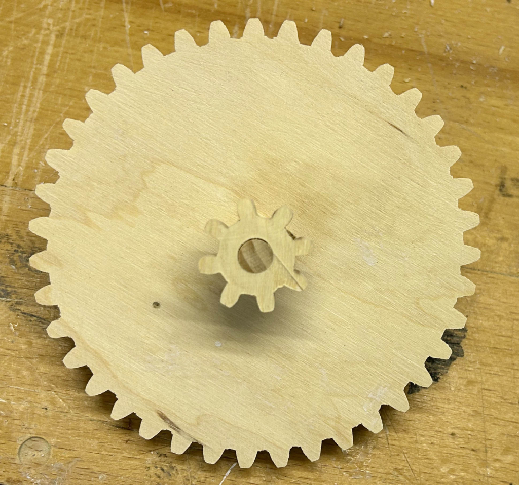
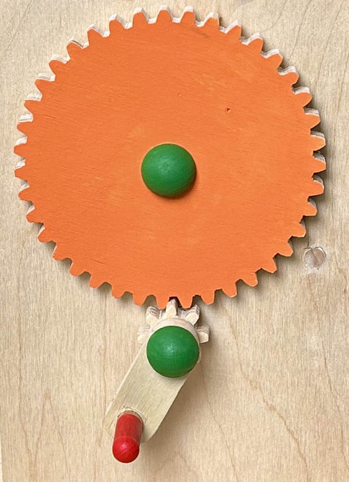
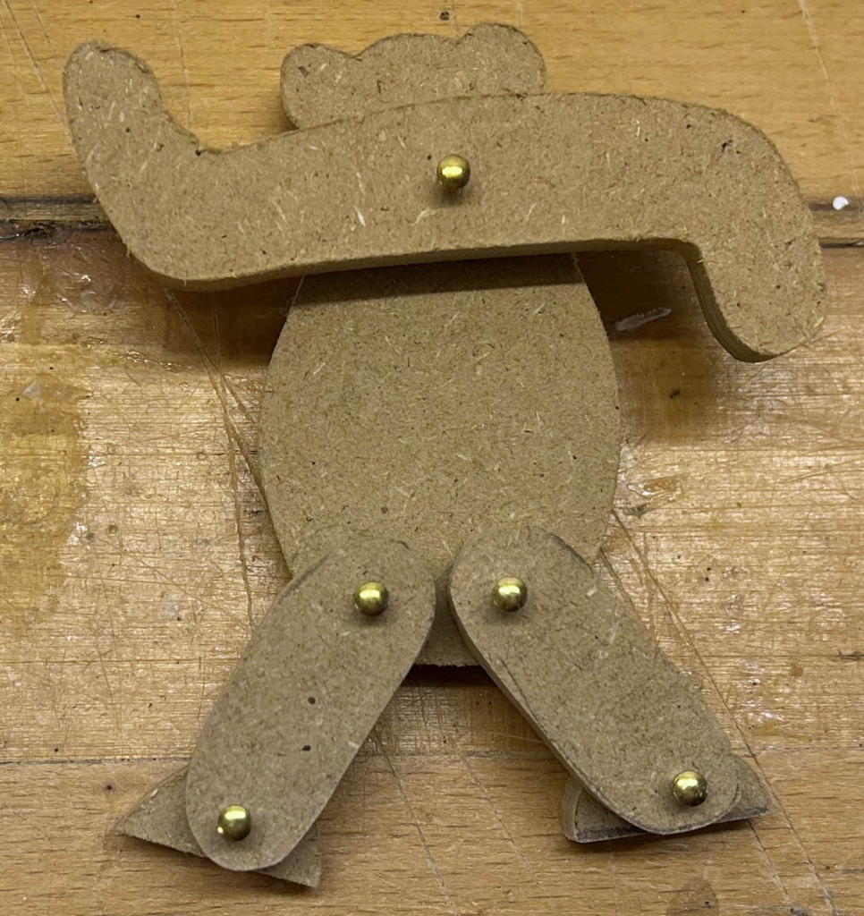
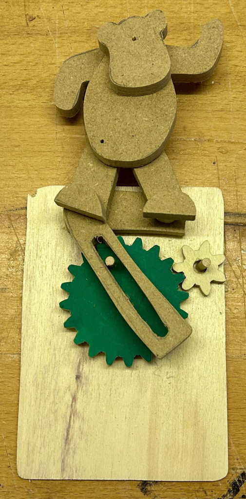
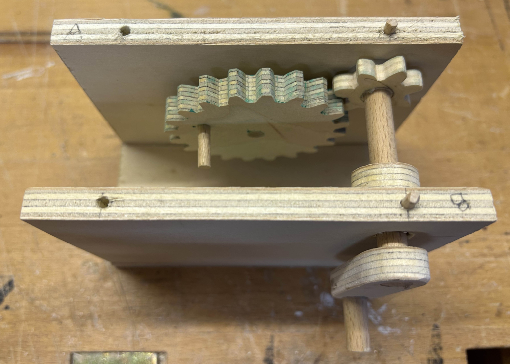
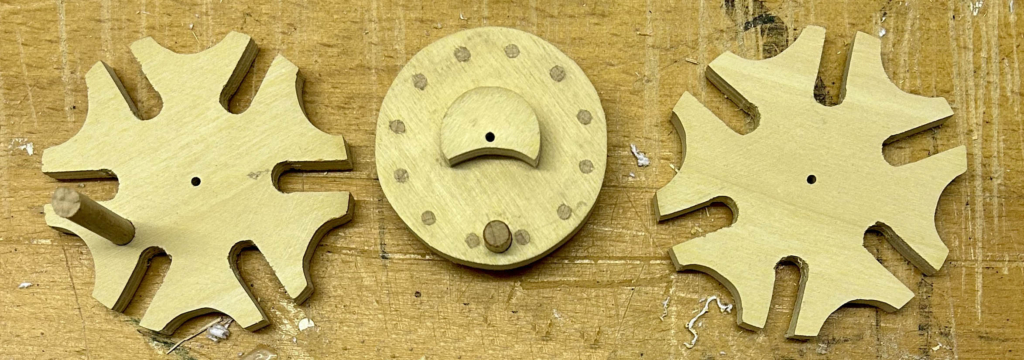
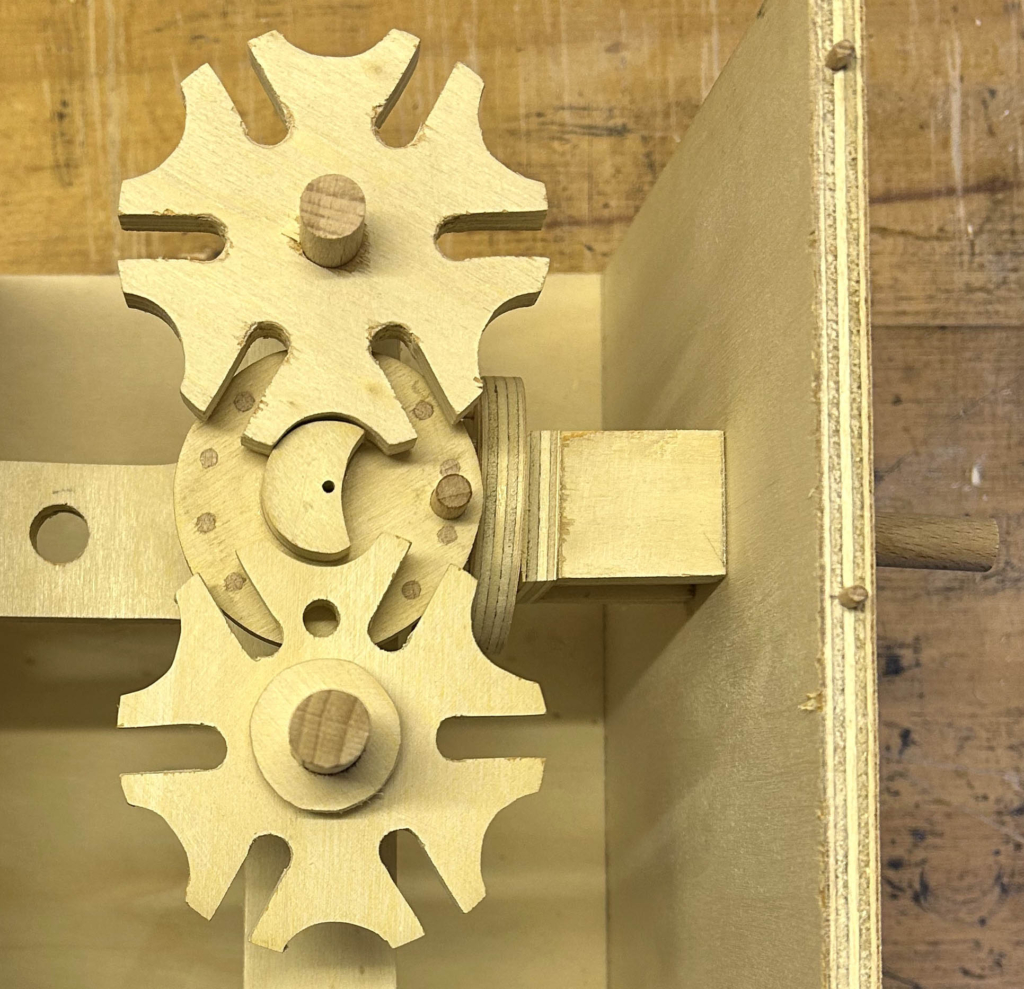
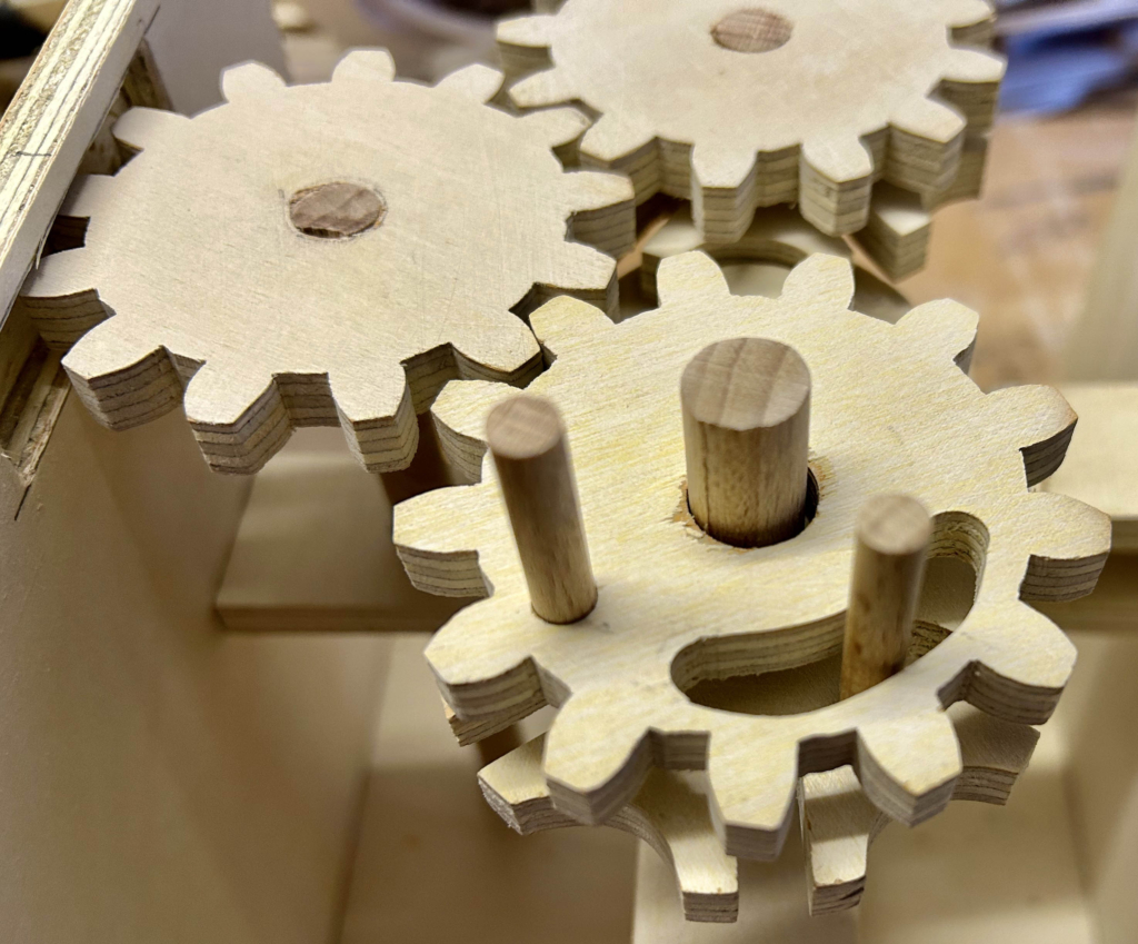
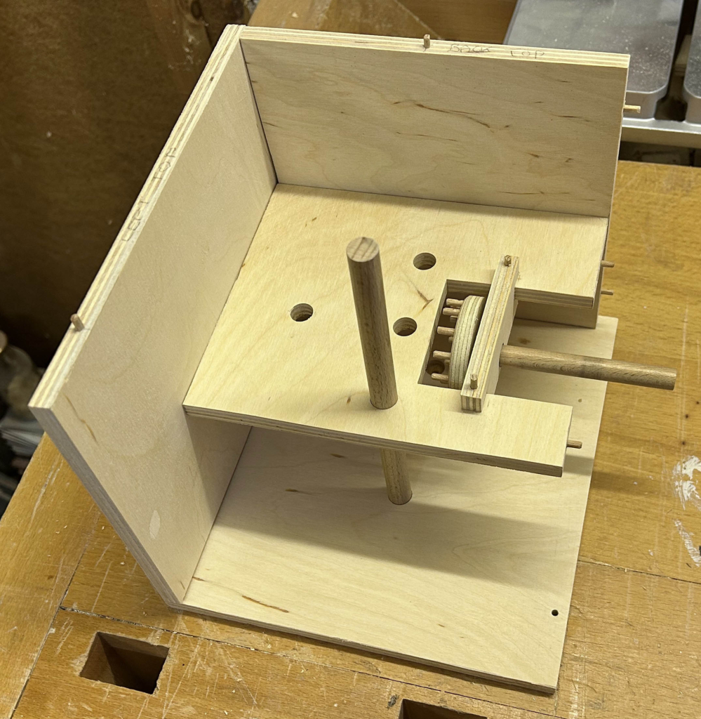
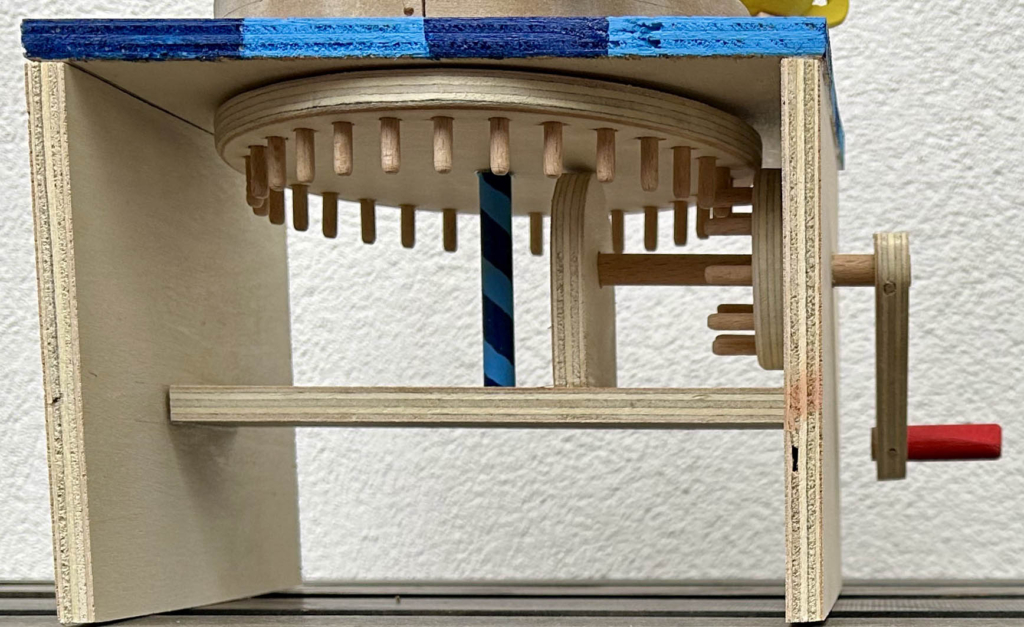
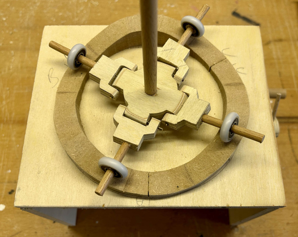
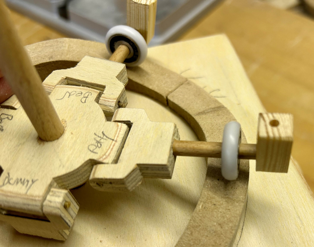
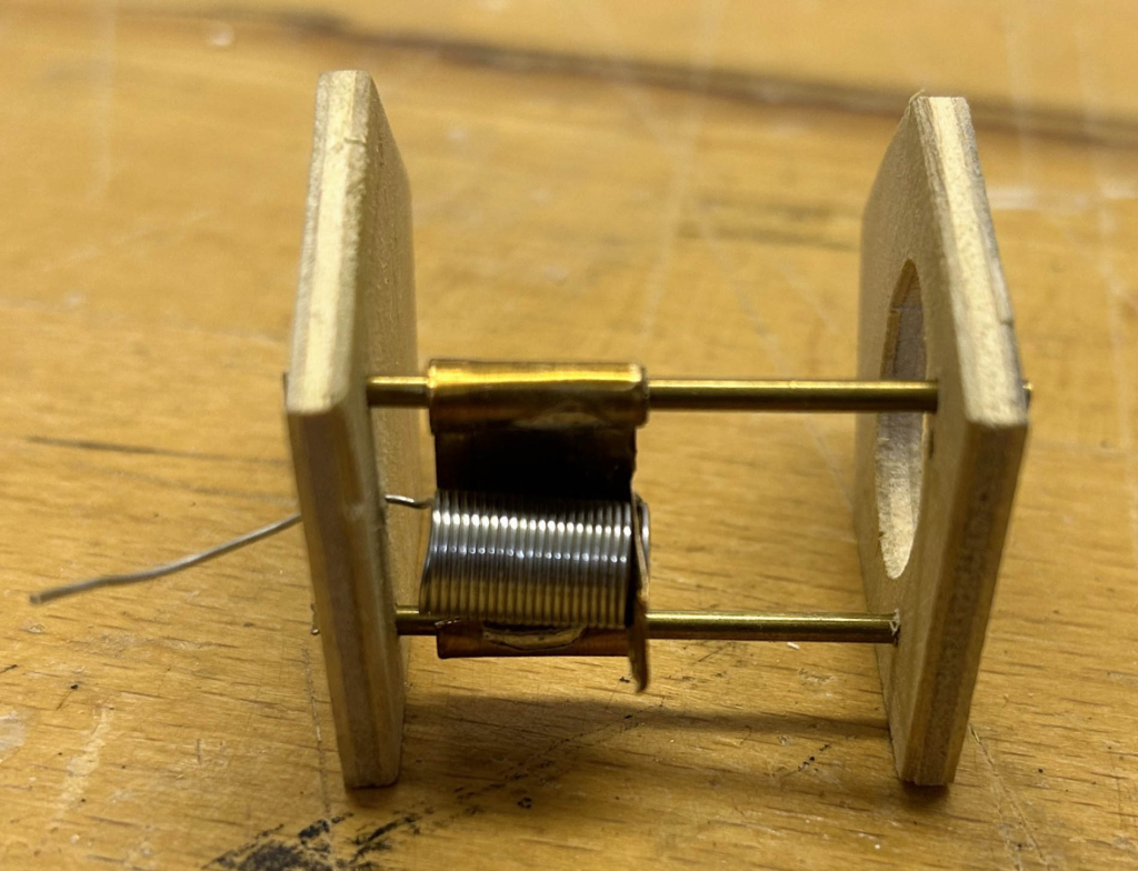
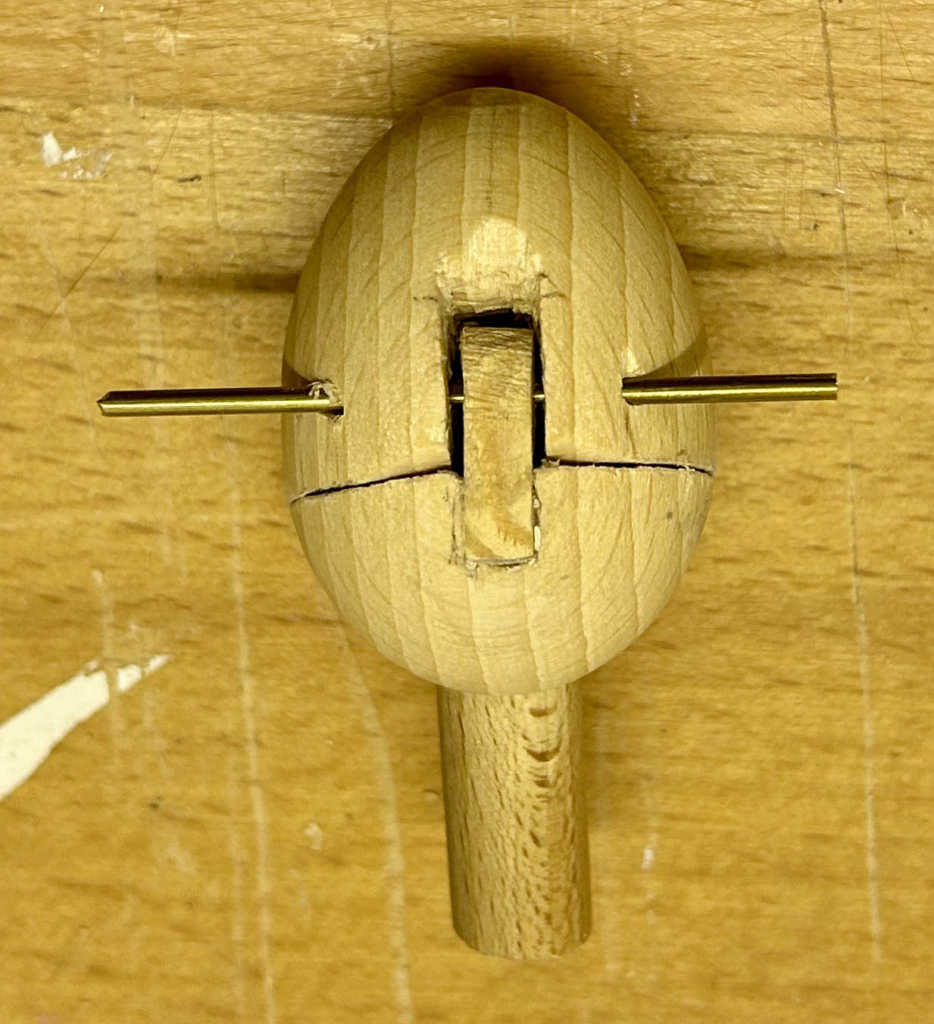
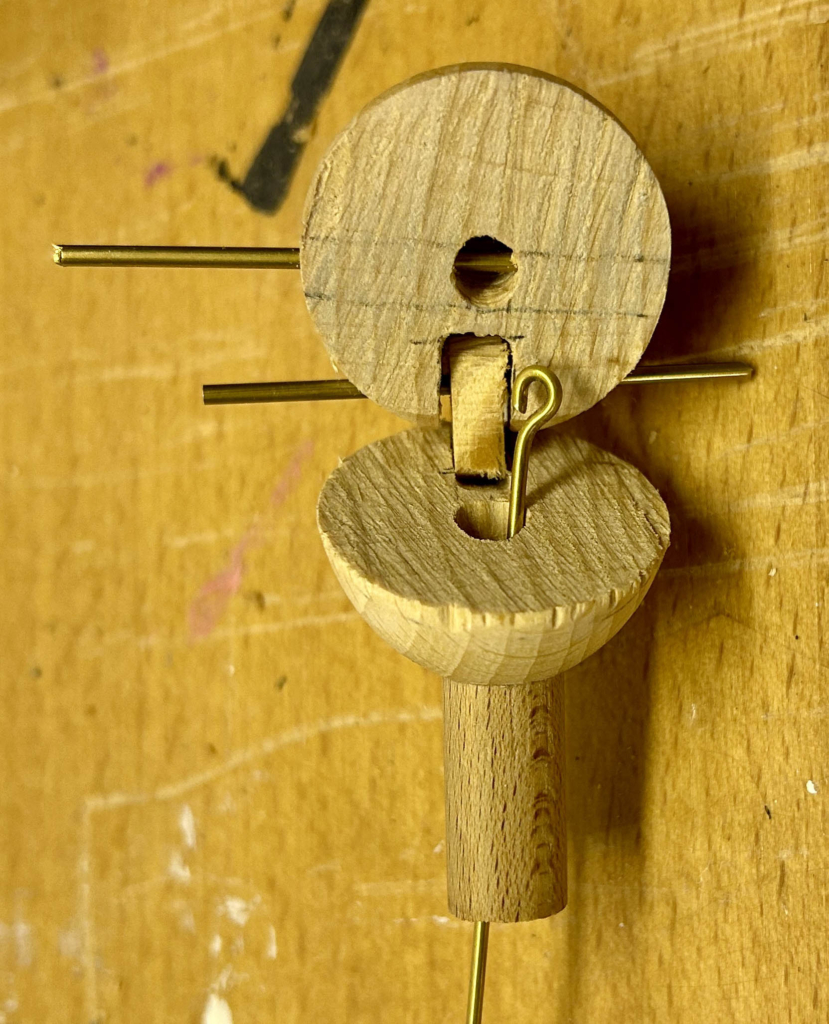
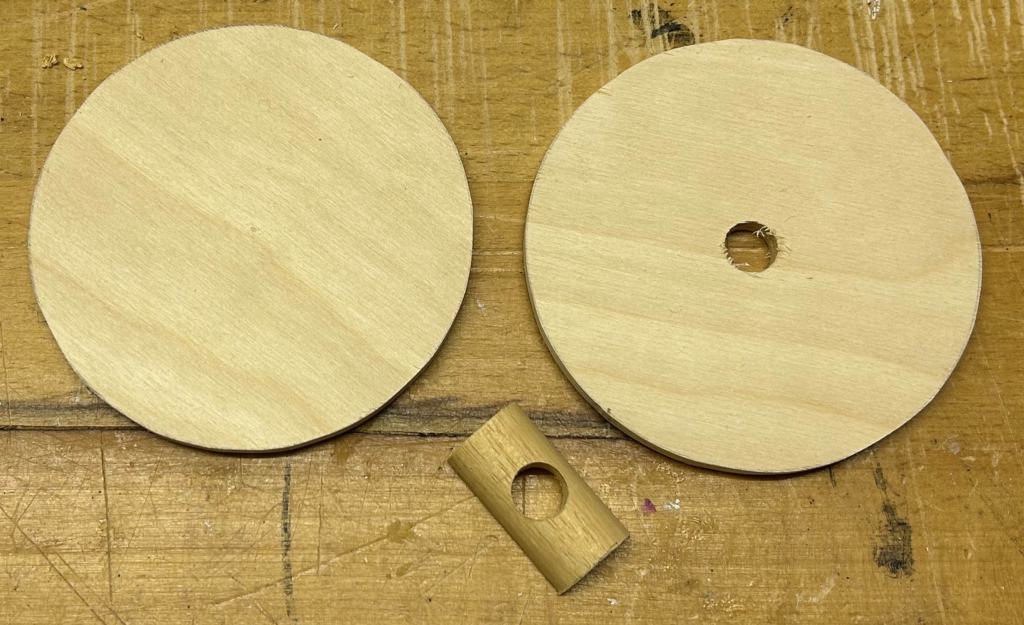
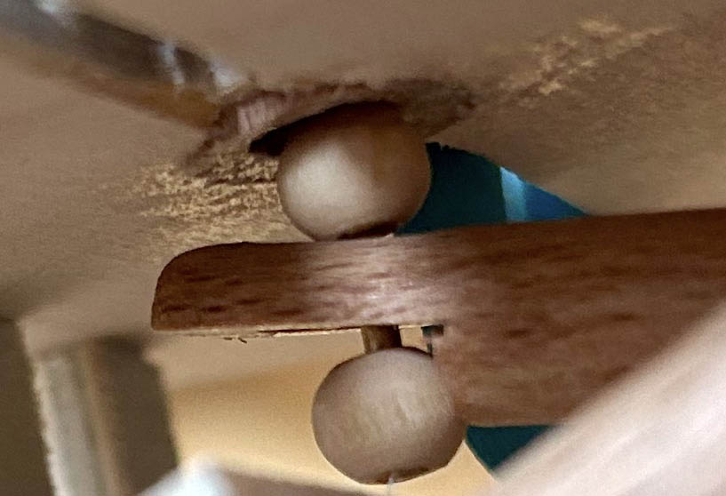
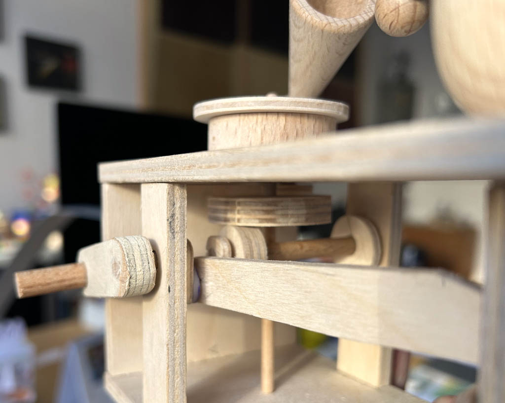
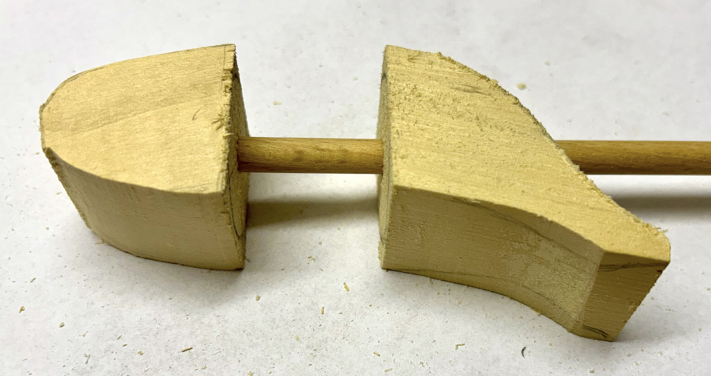
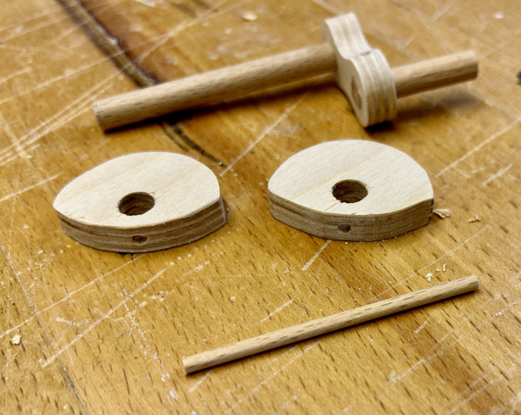
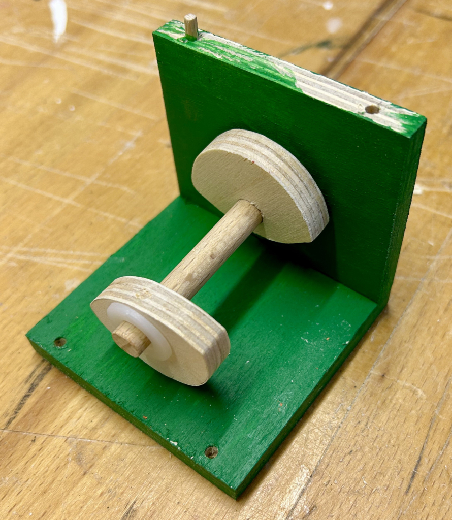
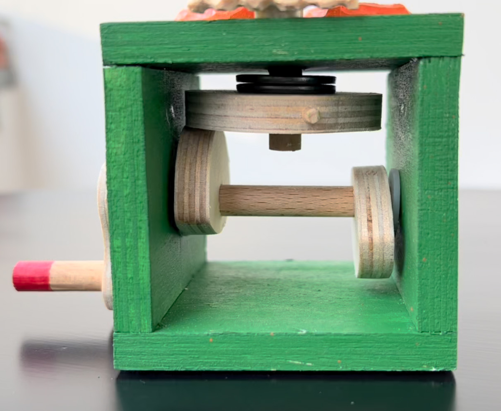
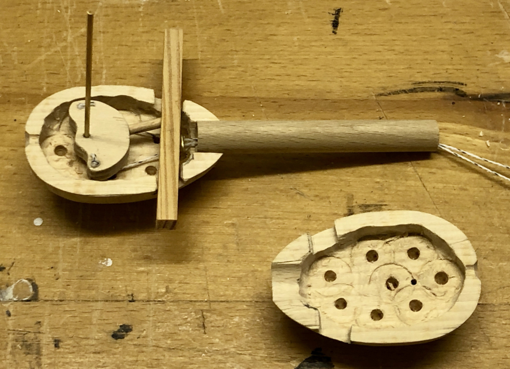
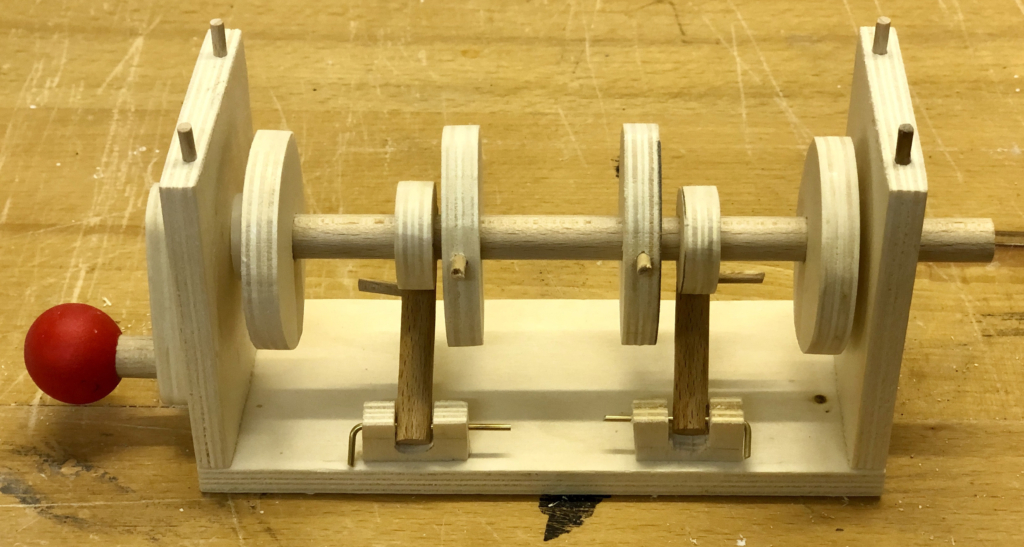
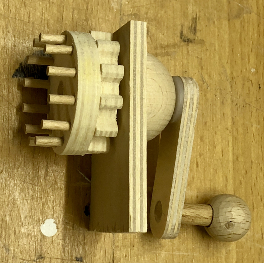
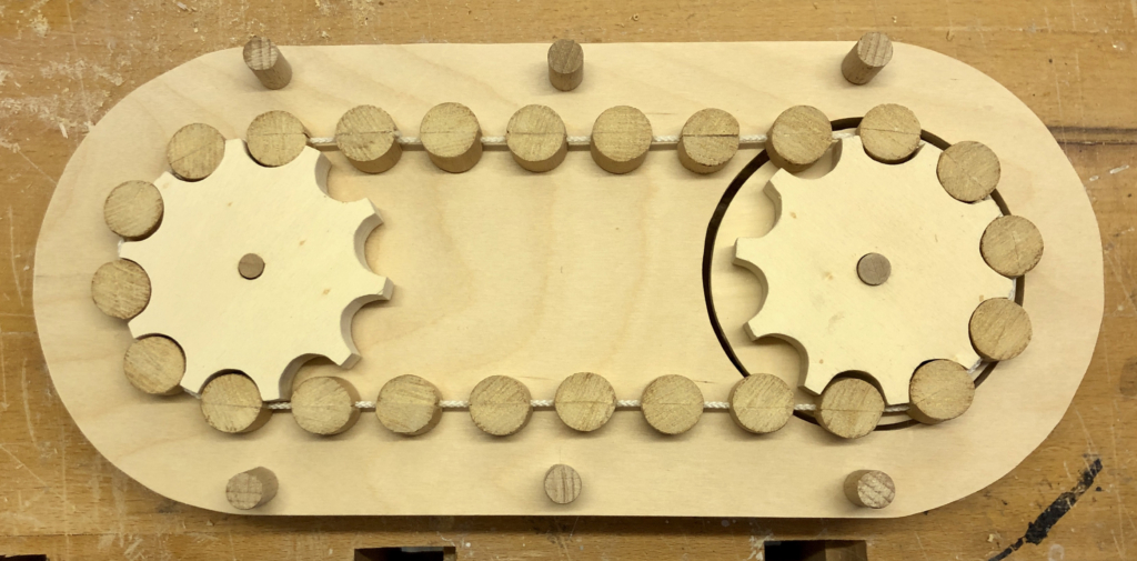
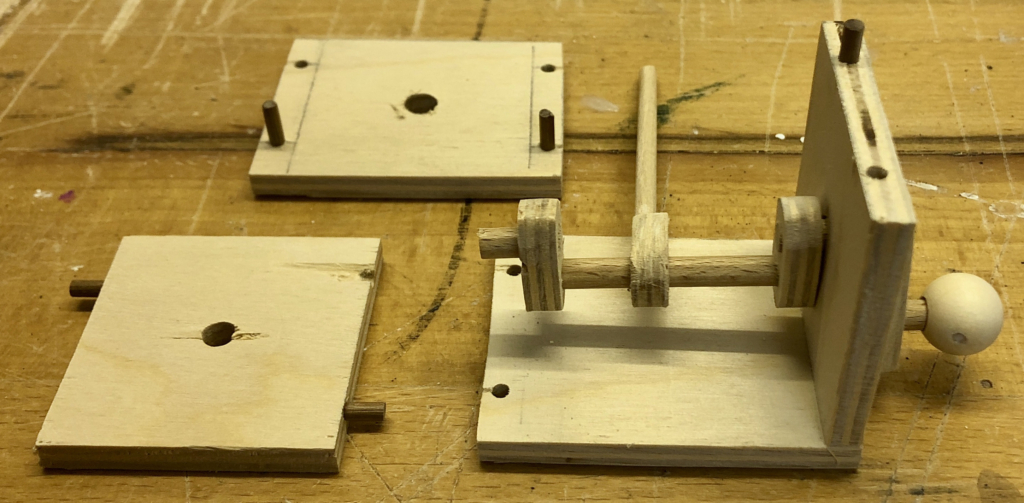
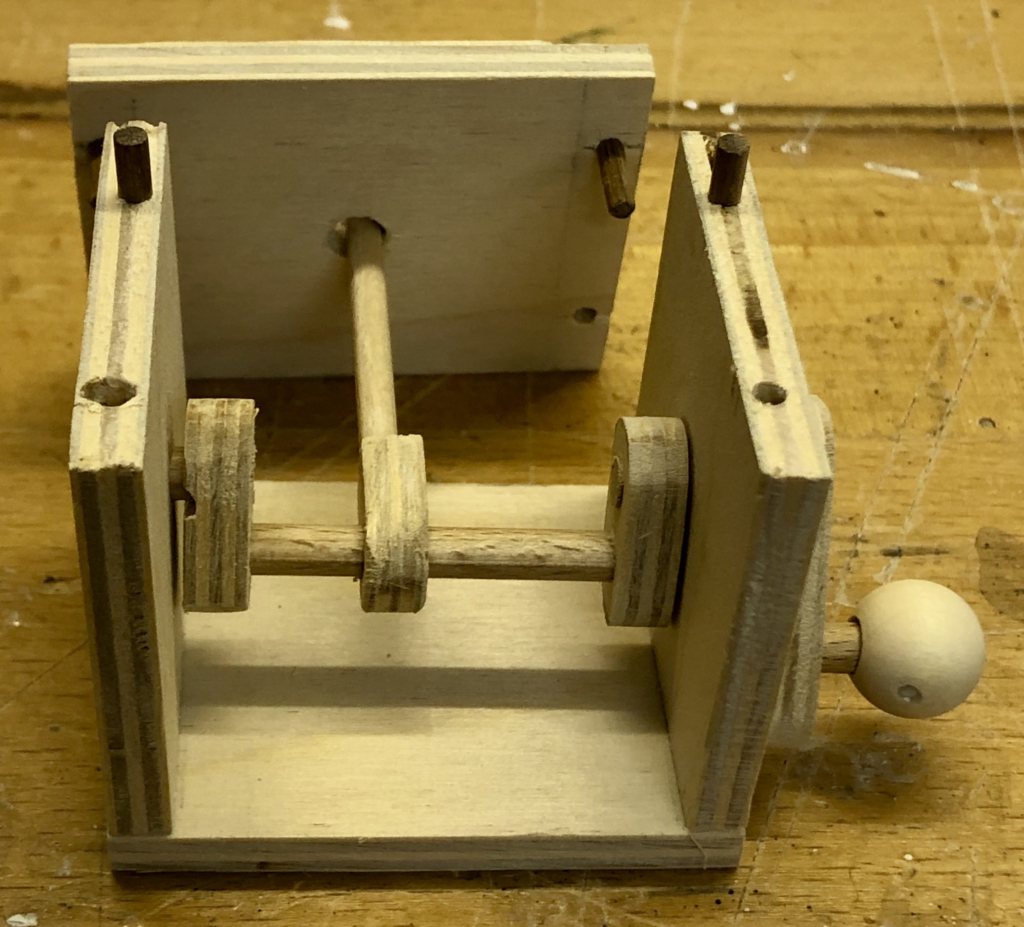
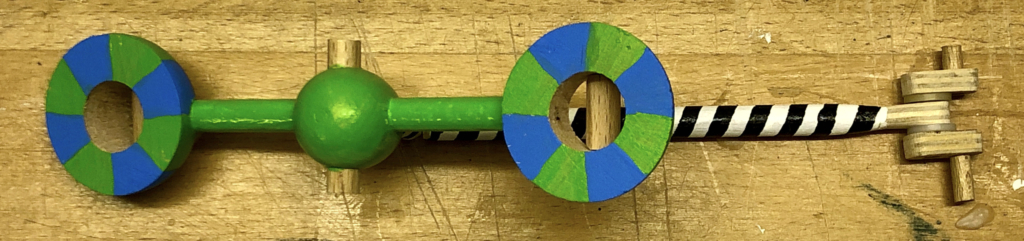
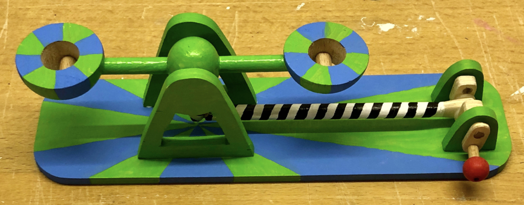
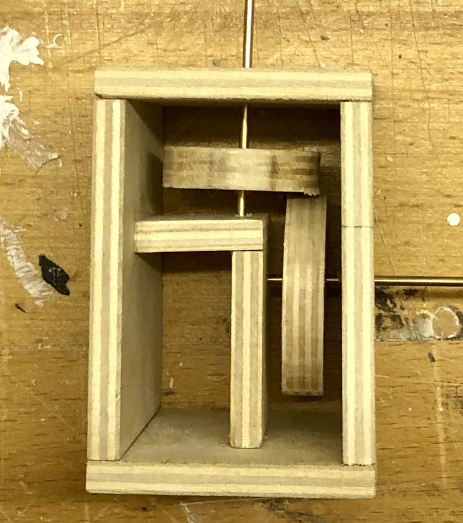
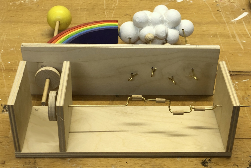
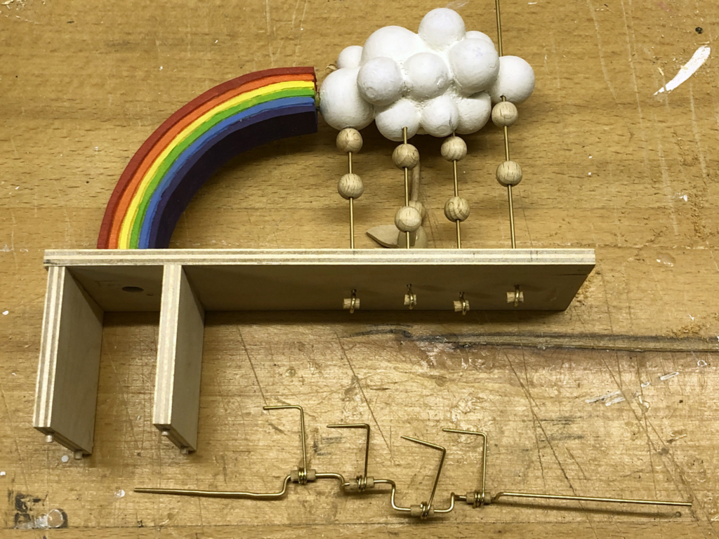
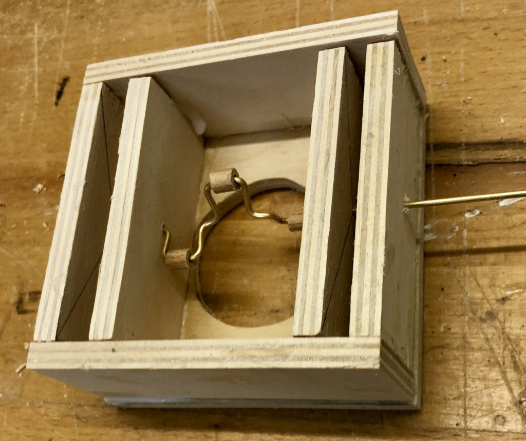
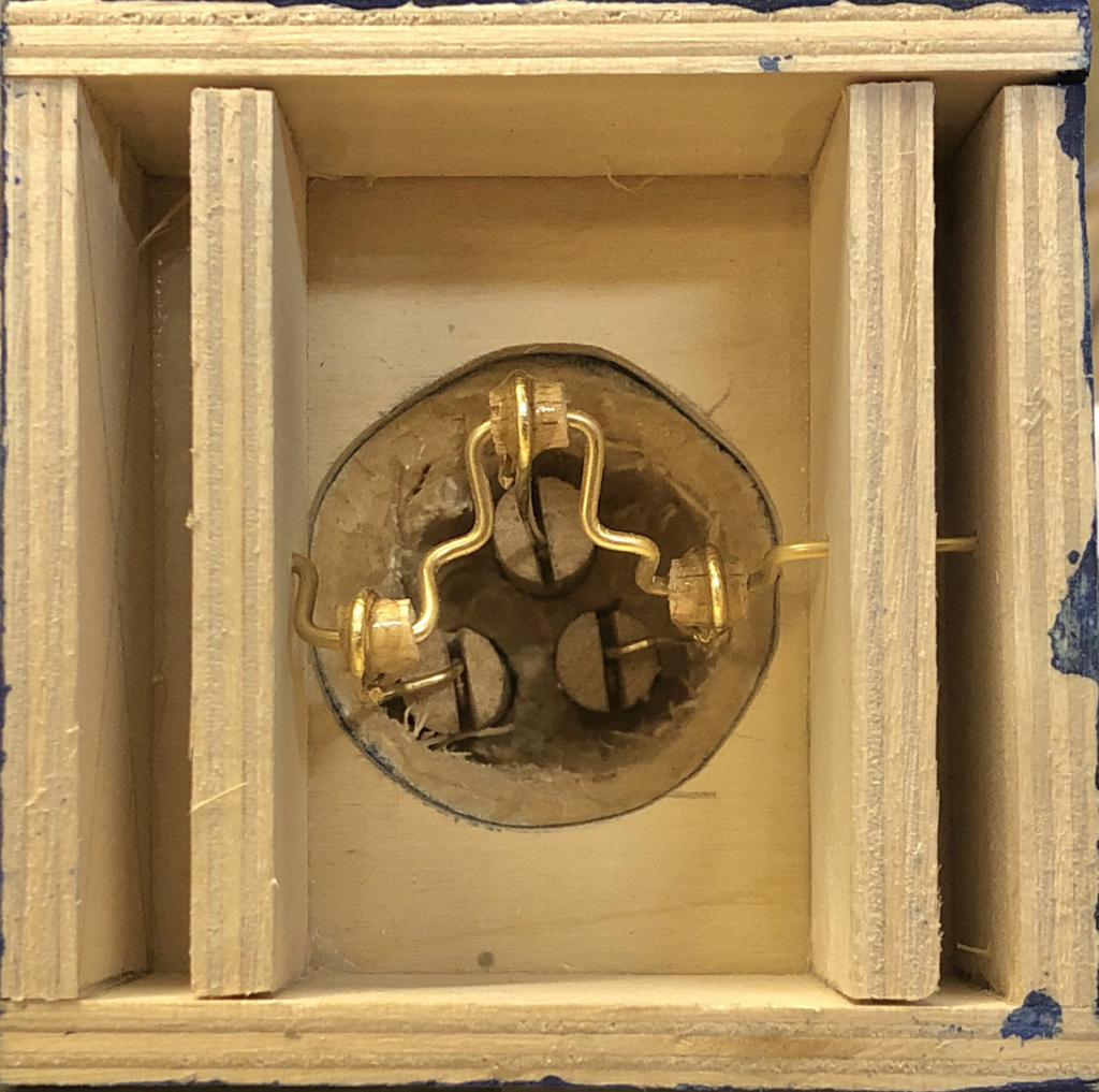
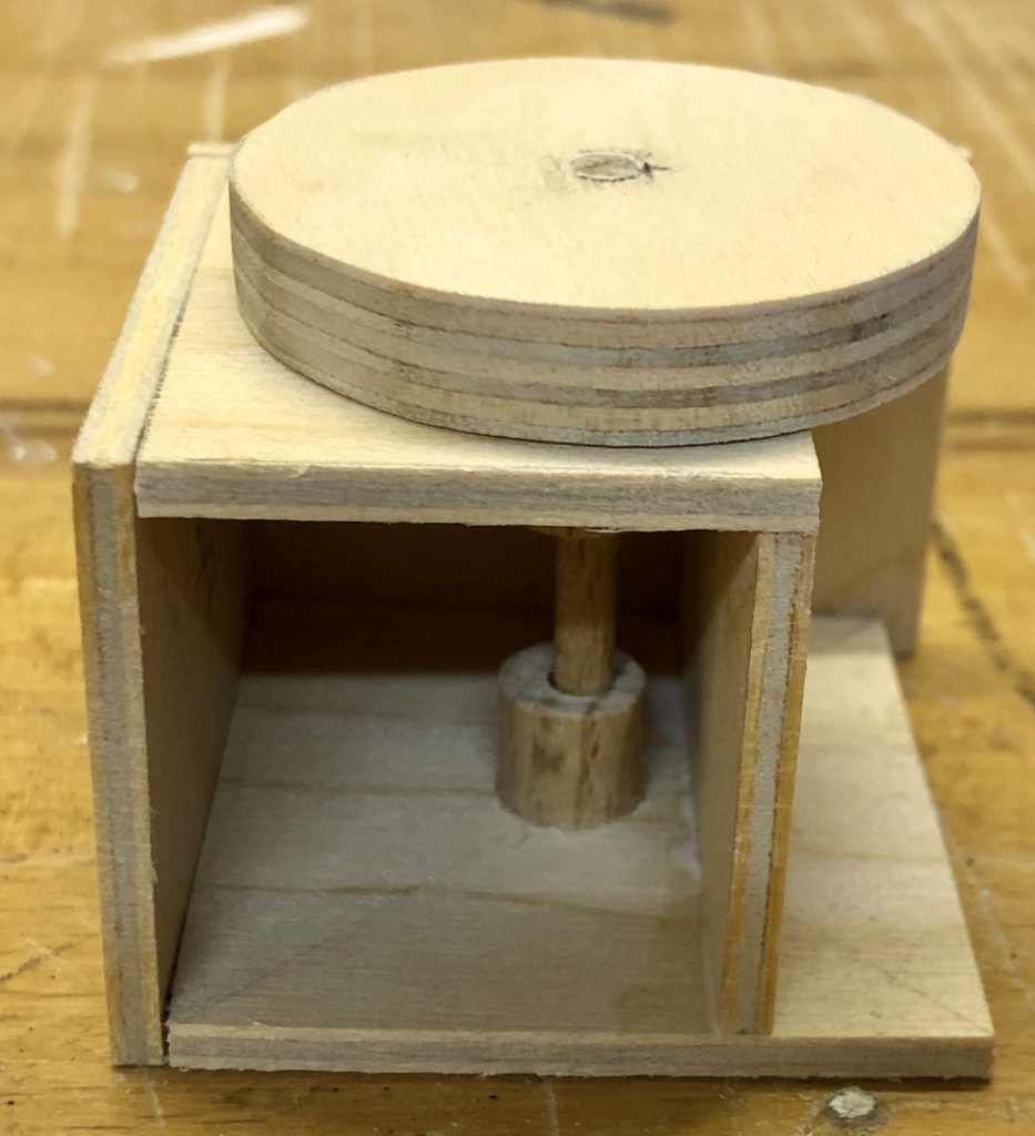
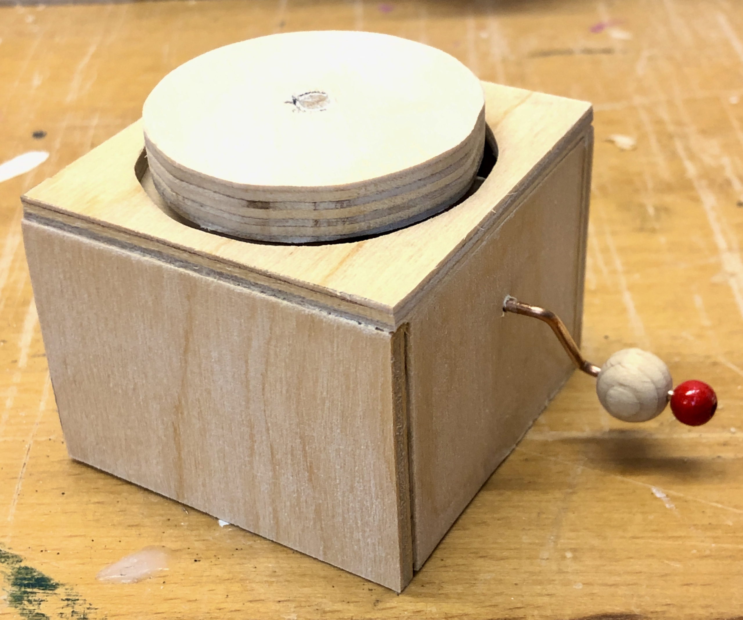
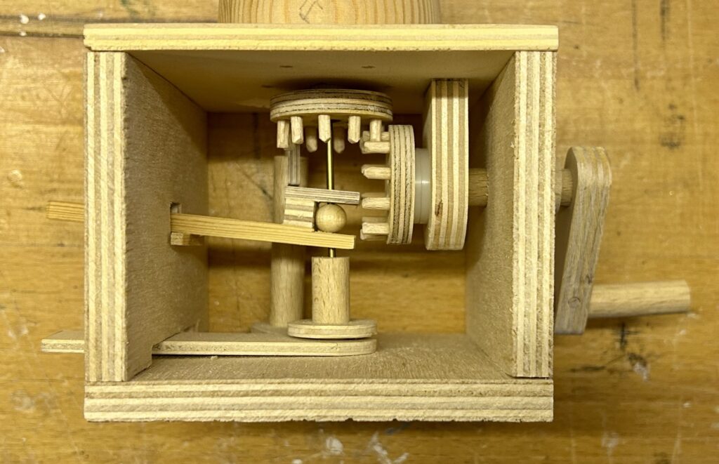
The 10 mm diameter hollow neck passes freely through both parts of the body to end in a pinwheel in the base. Turning this pinwheel turns the neck which turns head and there is nothing to stop it from turning endlessly. A wooden ball is glued to the brass rod which opens the mouth. Lifting this ball opens the mouth.
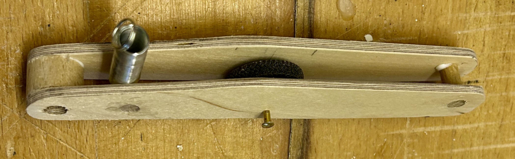
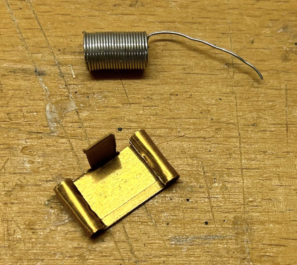
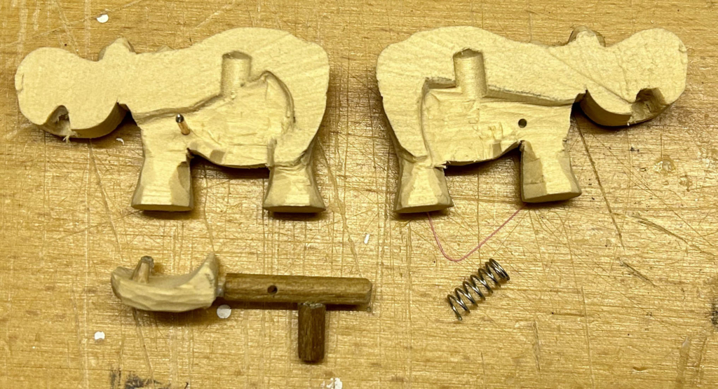
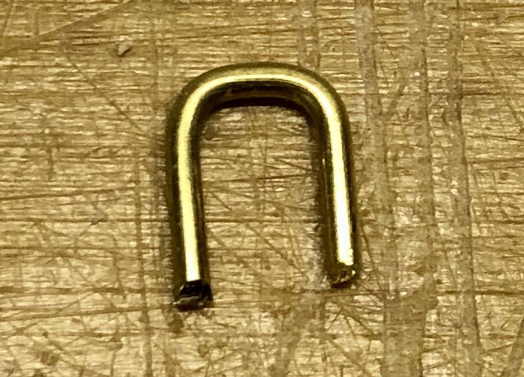
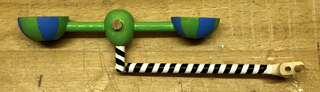
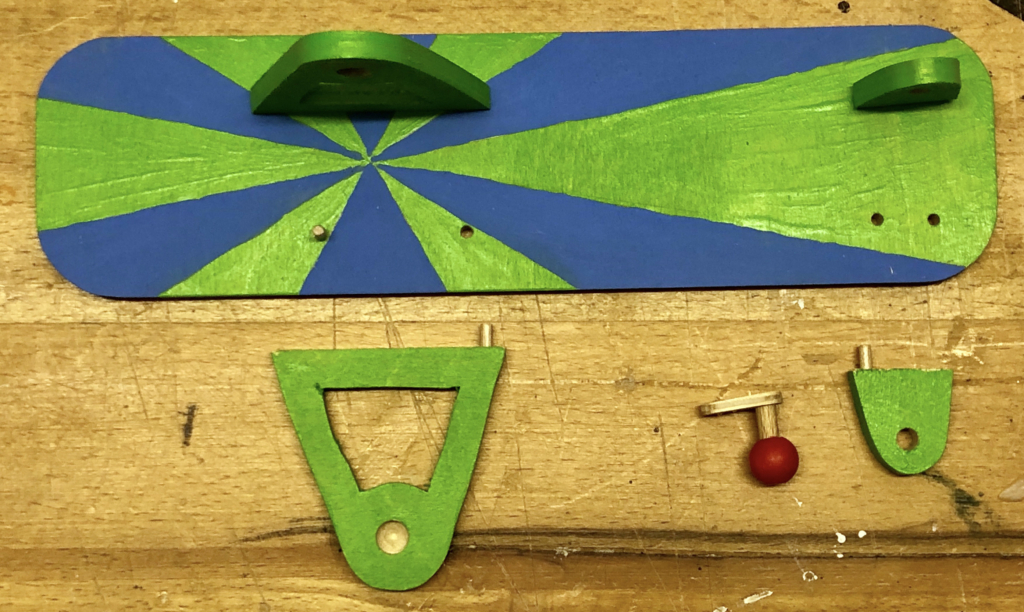
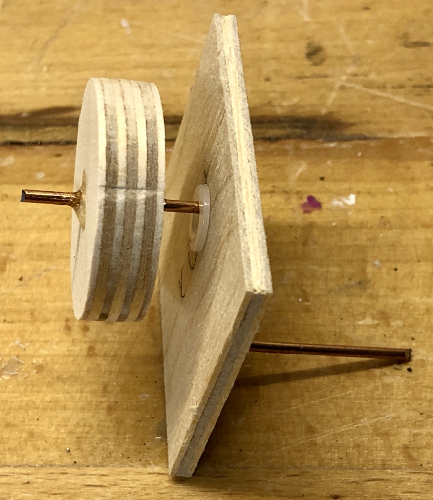
This curious looking lever fits around the ball, actively lifting or lowering it as required, without relying on gravity and without restricting the rotation of the brass rod as the head is turned by the pinwheel.
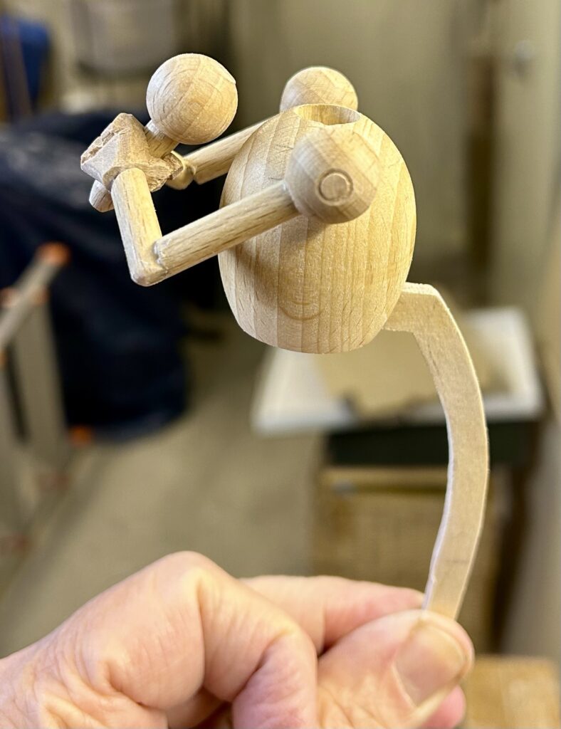
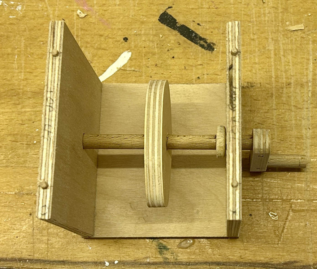
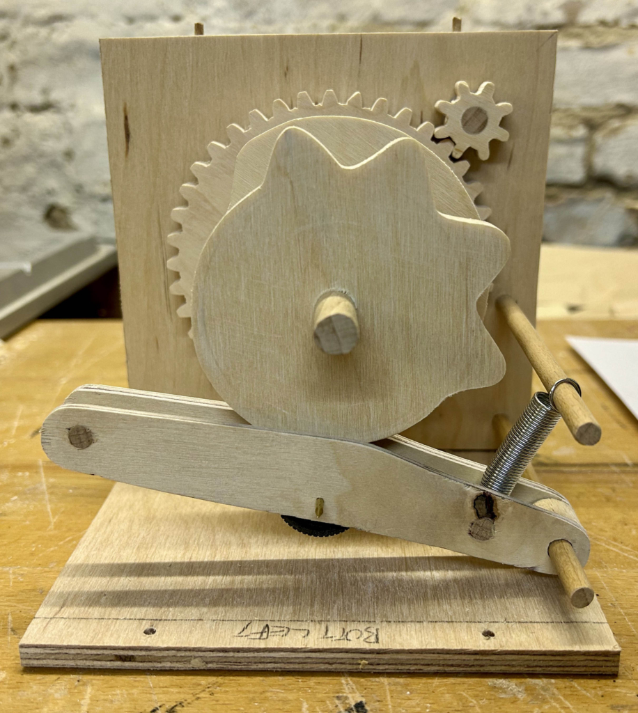
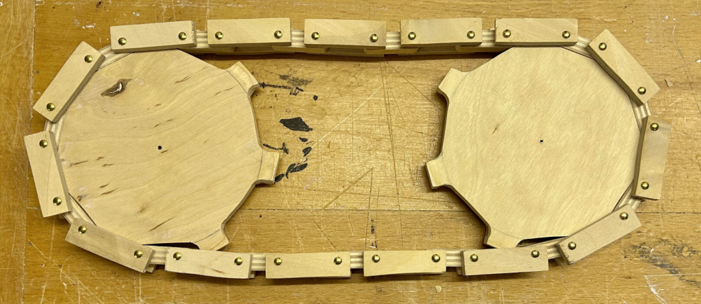
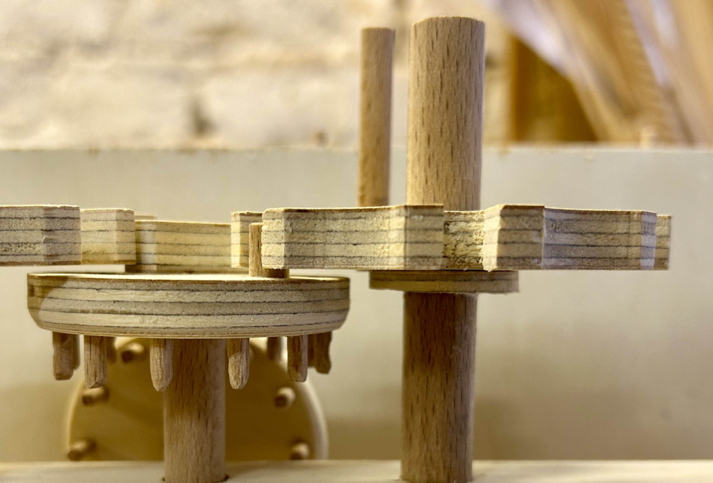
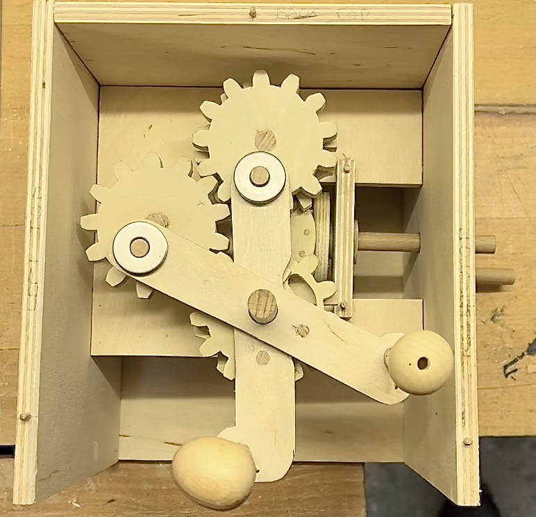
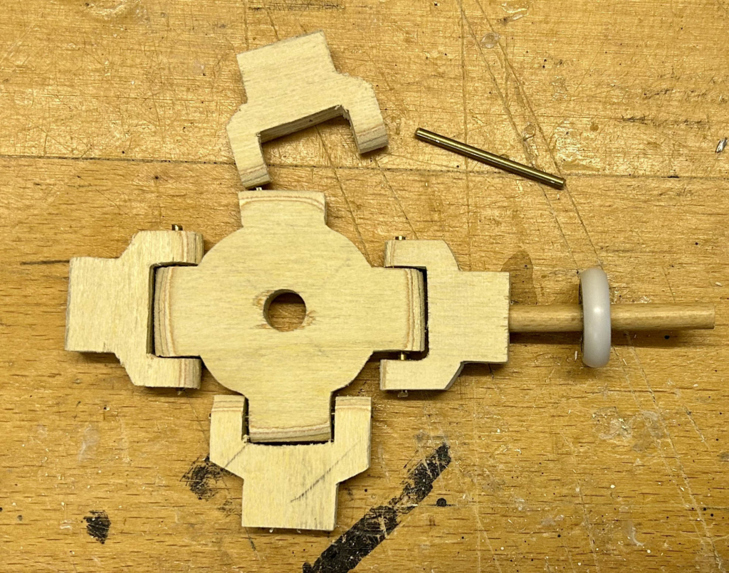
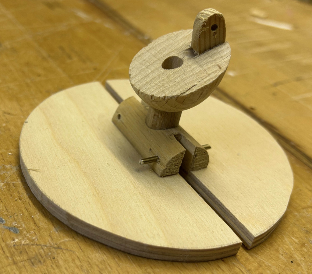
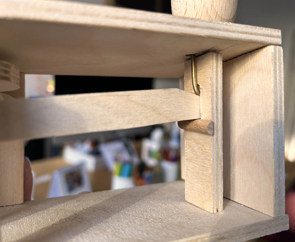
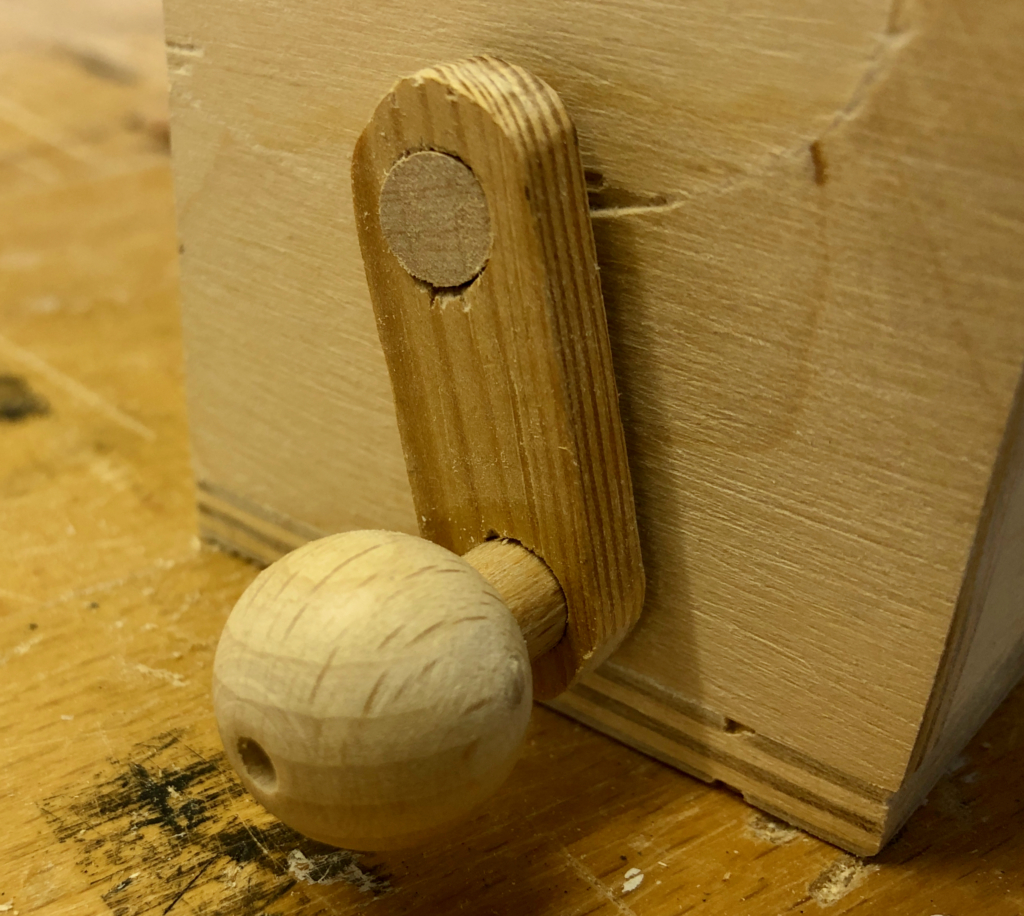
The upper body fits loosely on the hollow neck dowel and the lever can turn it to a limited extent. The resulting gesture is surprisingly human somehow, if a little childish.
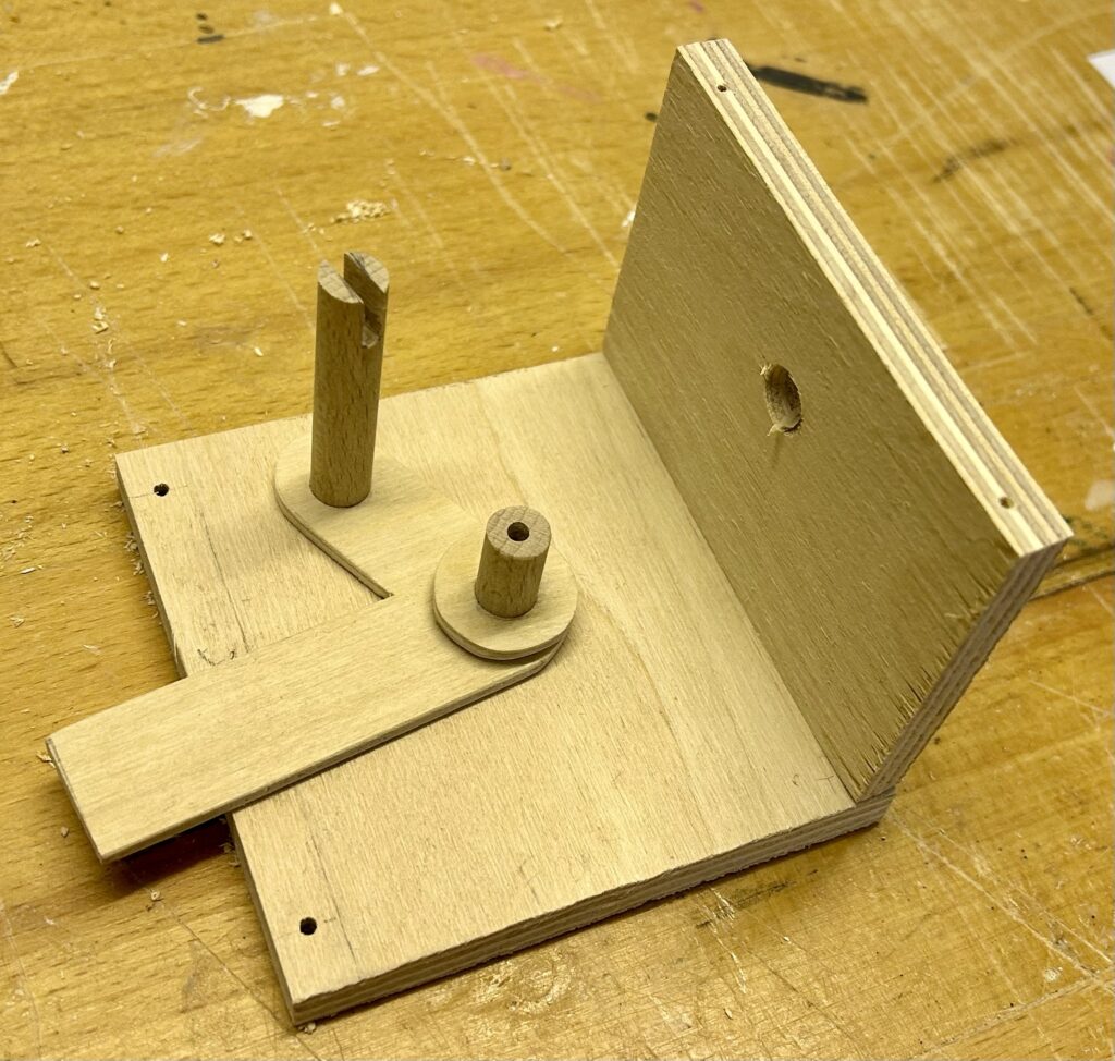
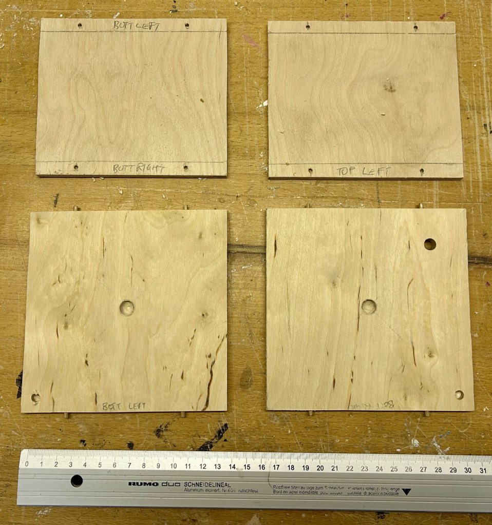
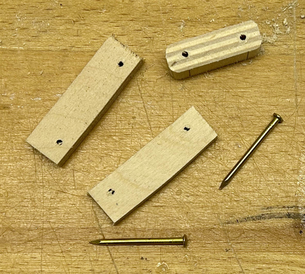
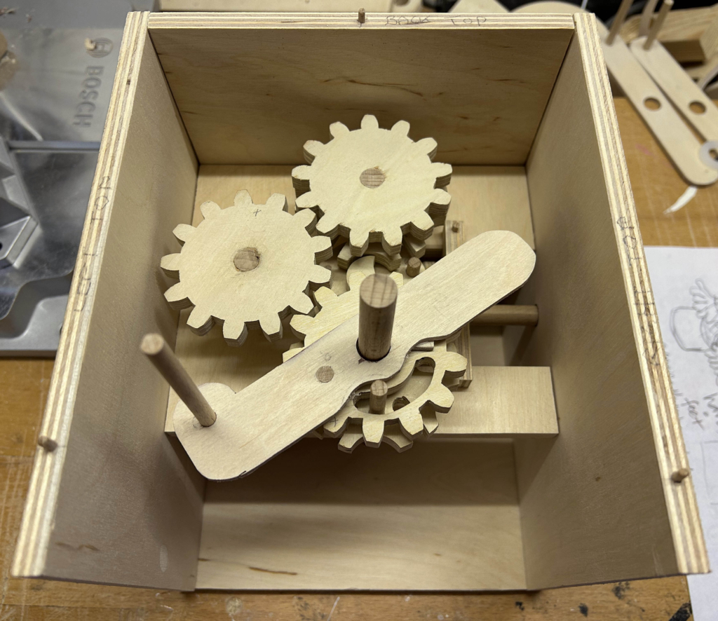
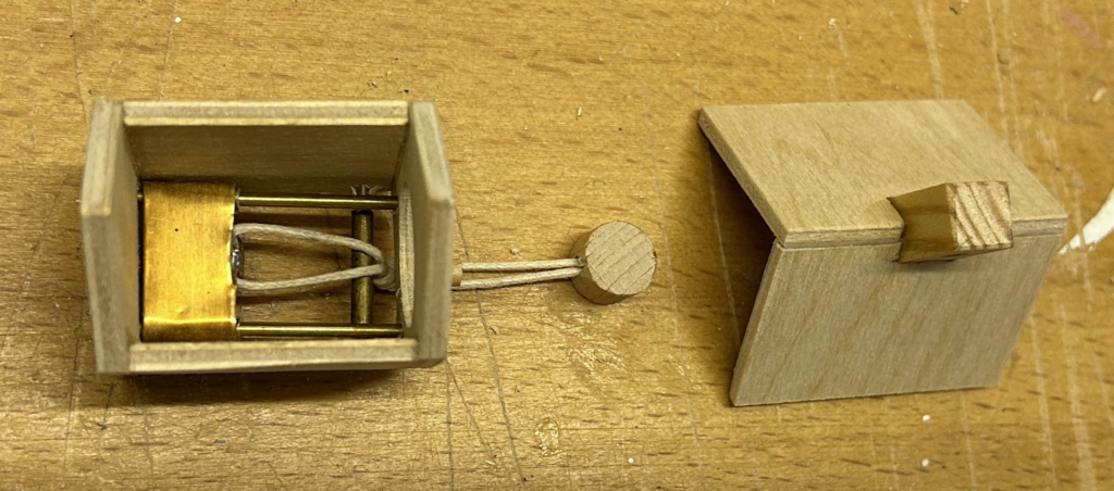
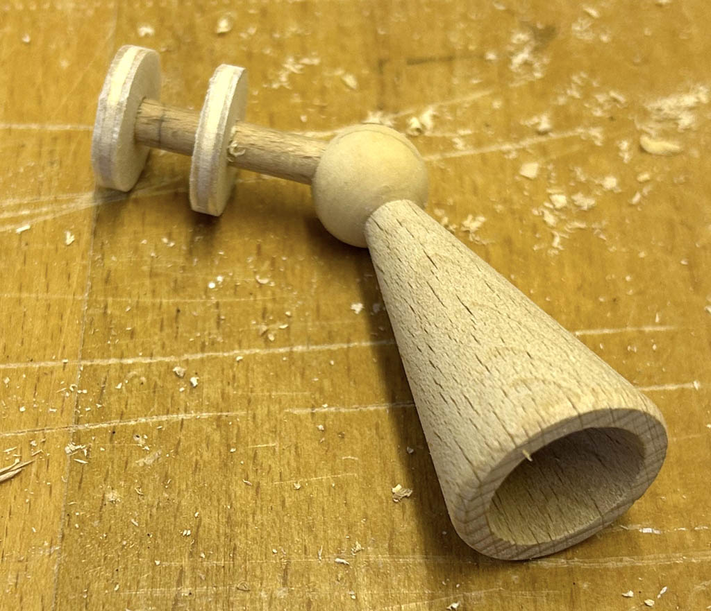
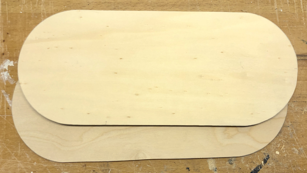
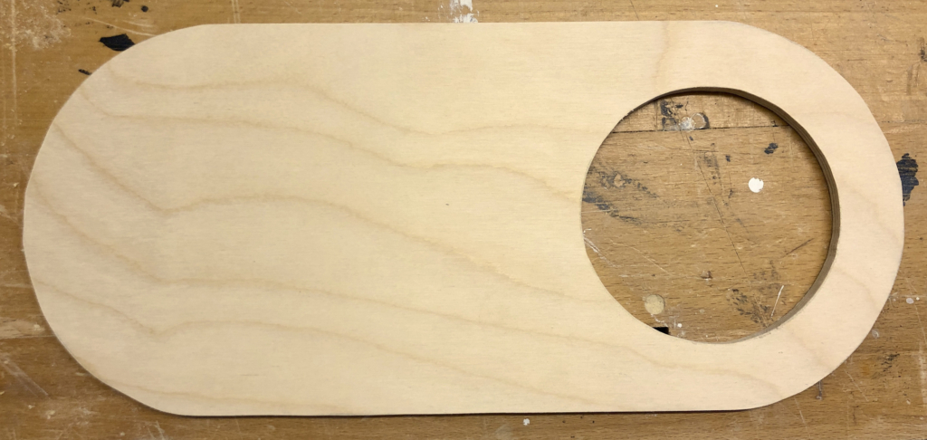
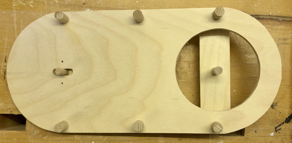
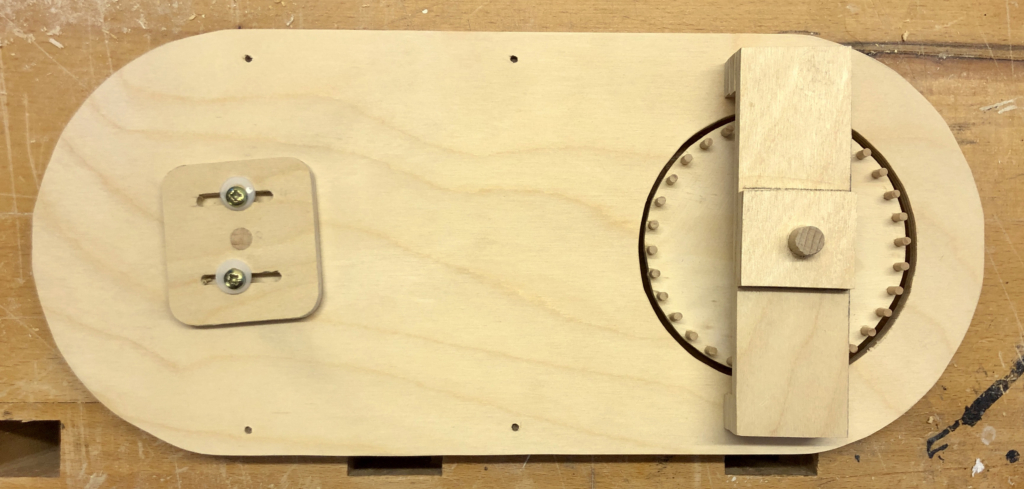
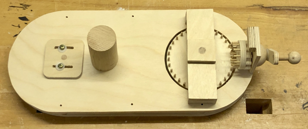
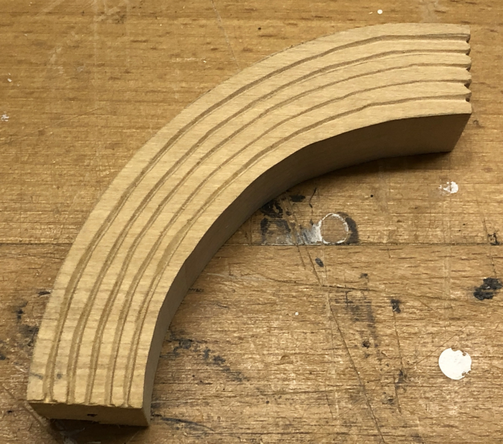
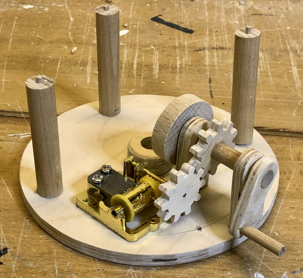
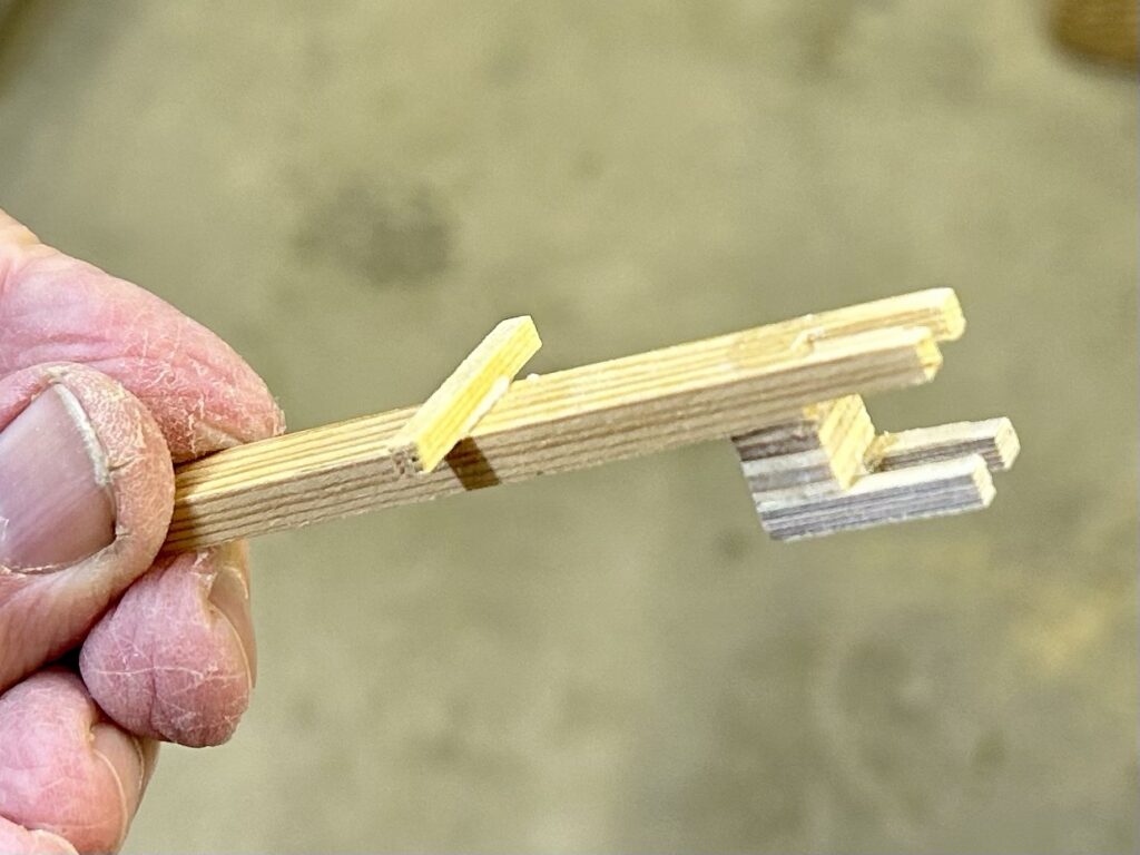
The curved lever fits into the slotted dowel. This dowel is moved by a lever protruding out of the left side of the box. The centre of rotation is aligned with the centre of the hollow neck.
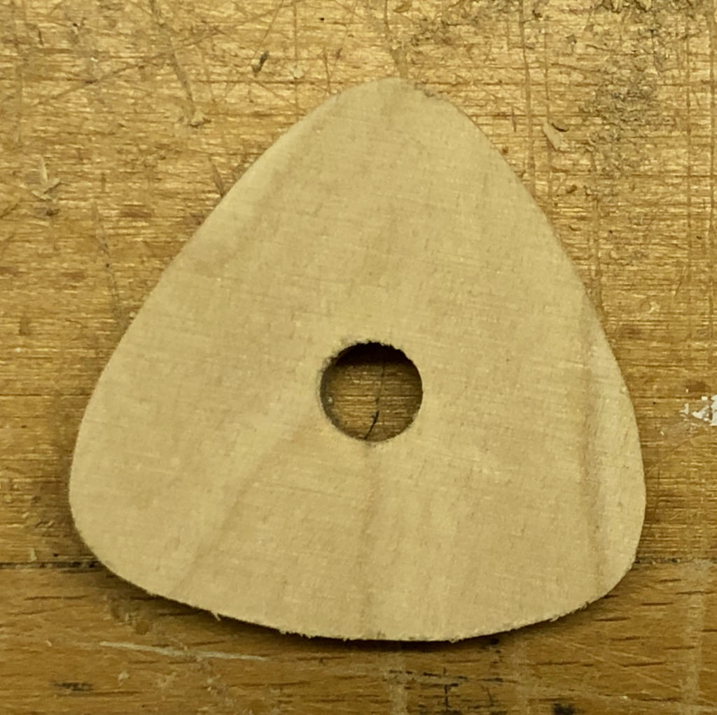
The brass rod to open the mouth fits loosely into a hole drilled in the centre of the dowel glued to the base. This means that the brass rod remains vertical even as the “curious-looking” lever moves through an arc, lifting the rod up and pulling it down
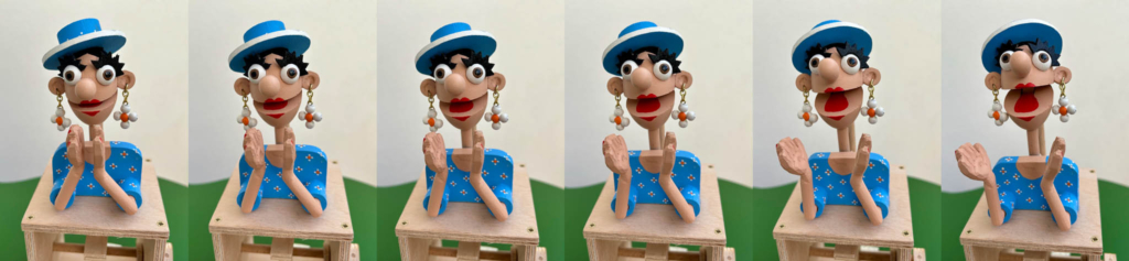
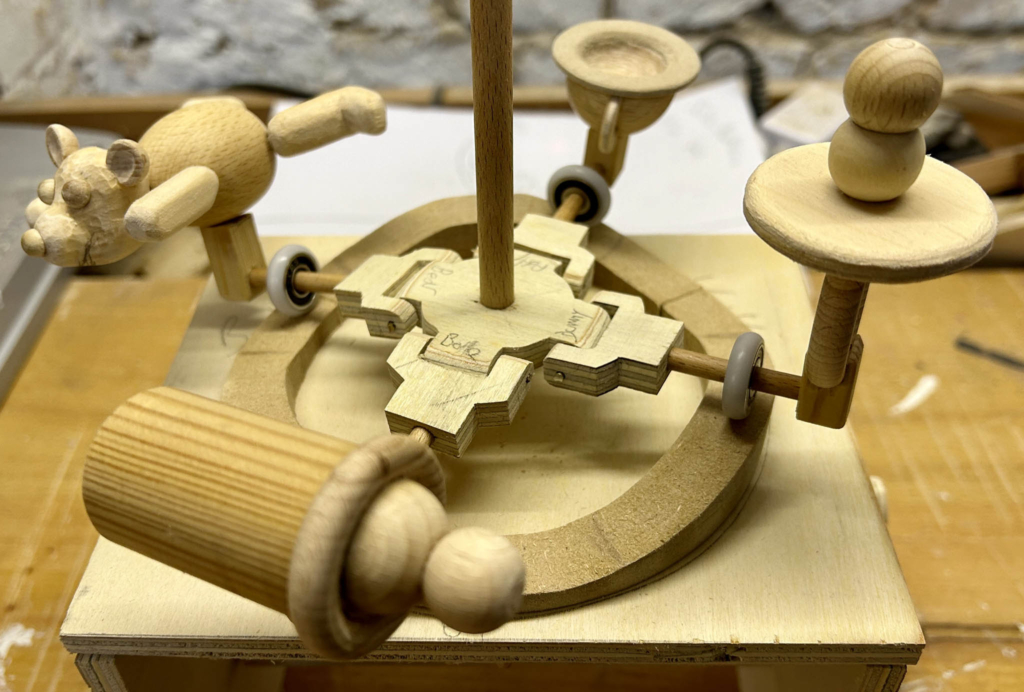
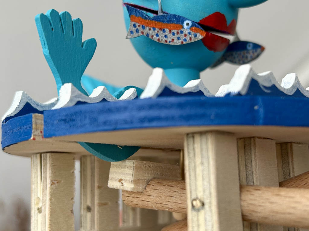
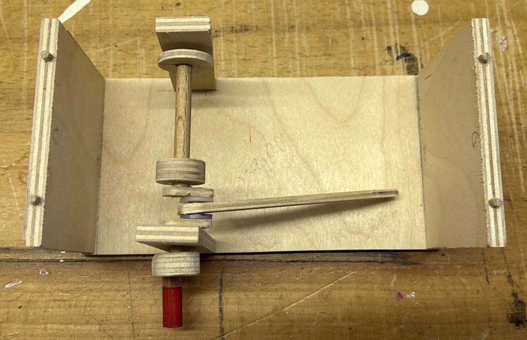
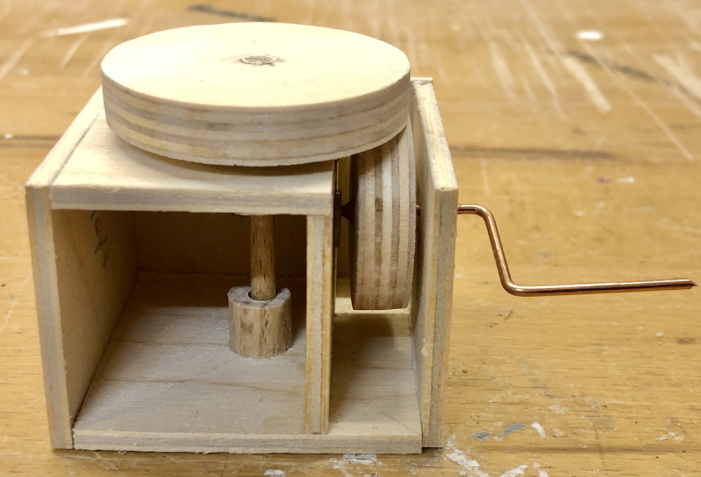
So, on the left side there are two levers – the lower one to turn the upper body, the upper one to open & close the mouth. On the right side there is a crank to turn the hollow neck, which turns the head. If you just jiggle this, it will jiggle the head back and forth. If you fully turn the crank, the head will turn completely around. If you keep turning, then the head will keep turning and the centrifugal effect will make the hair fly out sideways.
The Handle
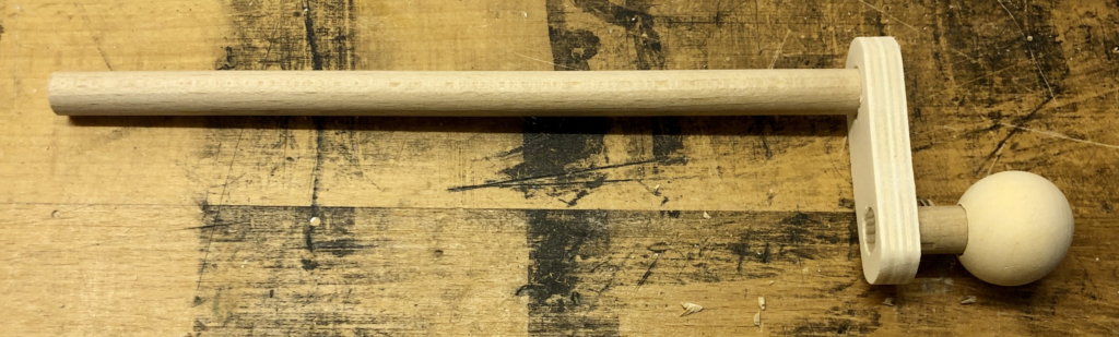
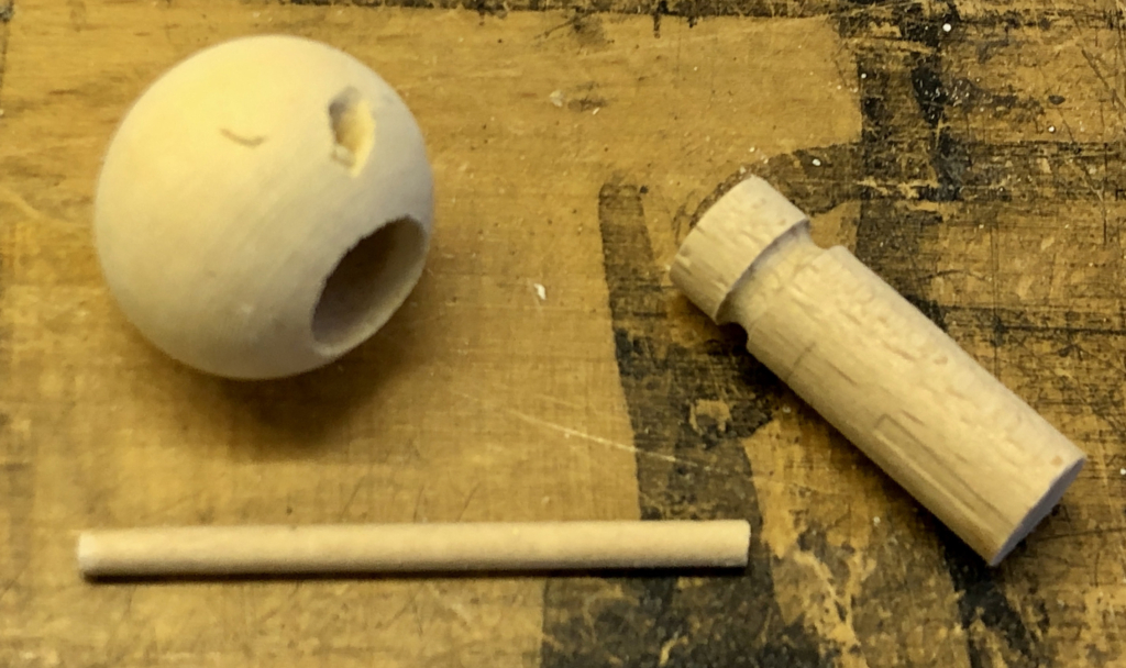
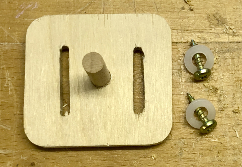
An automatist friend asked how I make the handle, which turns freely meaning that it does not have to slip between your fingers as you rotate the crank.
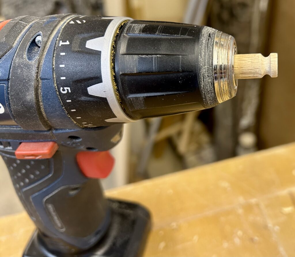
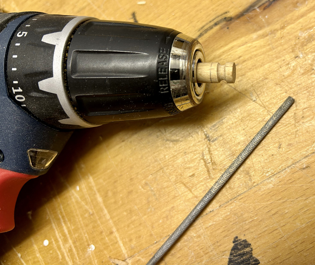
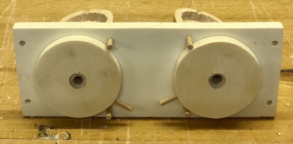
My battery-powered hand drill can hold drills with a diameter of up to 10 mm. It’s thus easy to fit an 8 mm dowel into the chuck. With a combination of saw, file and sandpaper I can then cut a groove near one end of the dowel. I haven’t got a lathe.
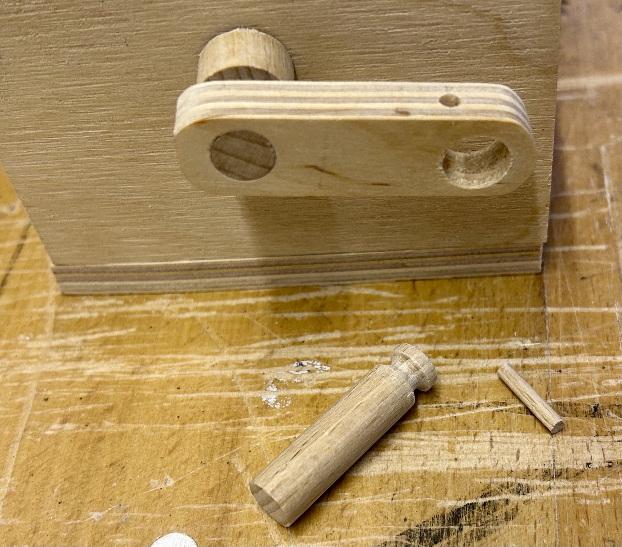
After drilling a hole slightly larger than the dowel, at the very edge of the hole I drill a 3 mm hole. A piece of 3 mm dowel can then be inserted to engage with the groove in the handle. This prevents the handle from being pulled out whilst allowing it to turn freely. Magic!
How does it work?
Using both hands, with a little practice, it’s possible to simultaneously operate both levers and the crank, not forgetting to sing a suitable song while doing that. To demonstrate it to someone else, you can always turn it around and work the levers from behind. I suppose that makes it more of a string-free desktop puppet rather than an automaton, but who cares? You move the levers and the crank and everything starts to move.
The hair is long and it moves quite convincingly so I would say “mission accomplished”. Now I have to learn the words to some more songs to extend my repertoire!