Video on Youtube – https://www.youtube.com/watch?v=6_SsgYUONhw
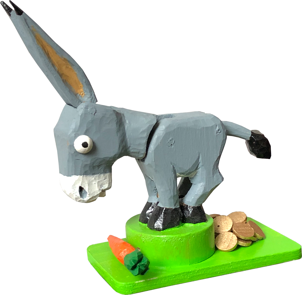
Goldesel plays a role in one of the European fairytales collected by the Brothers Grimm. All you had to do was say the word “bricklebrit” and the magical donkey’s droppings turned to pure gold ducats!
This wooden version of that fabulous animal has its own magic. Touch its single carrot and Goldesel will lift its head in wonder and, delicately used, Goldesel will waggle one of its ears. That can’t compare with the 24 carats heaped at the other end, but if you can find the one special, magical ducat, Goldesel will respond by politely lifting his tail. Unfortunately, so far despite lifting its tail “bricklebrit” doesn’t seem to have the desired effect with my limewood version. Maybe it’s my pronunciation, but I haven’t given up hope yet. Maybe your version will work better?
How to make your Goldesel
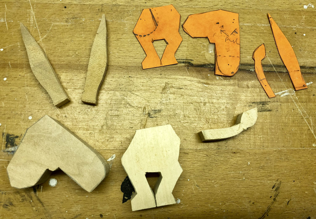
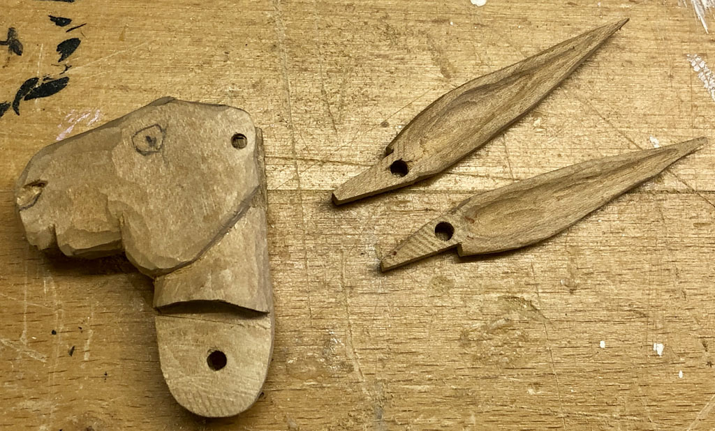
Draw one ear, a head, a tail and the body with legs on some stiff card. Bigger heads look cute as they suggest a young animal. Use some pins to try out the movement and work out the best place for each hinge. When you are satisfied, trace the shapes onto wood of the right thickness. At this stage, I actually scroll cut 3 ear shapes, as it looked close enough to a carrot shape to be able to carve it.
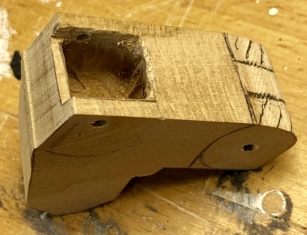
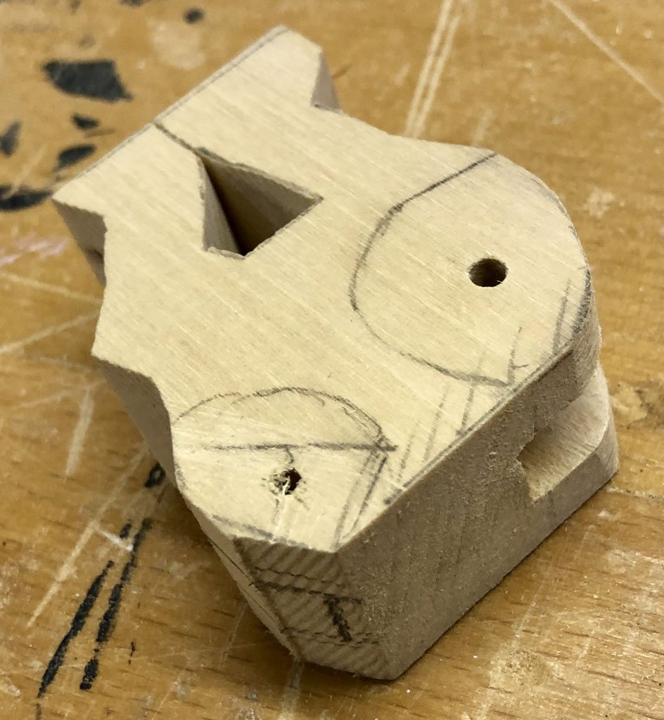
Drill two holes through the head for 3 mm dowel. For the hinge between the ears and the head drill the head so that the dowel is a tight fit. For the head to move freely on the dowel in the body, drill a second hole in the neck for a loose fit. Drill the holes where you had put the pins in the card when you checked the movement.
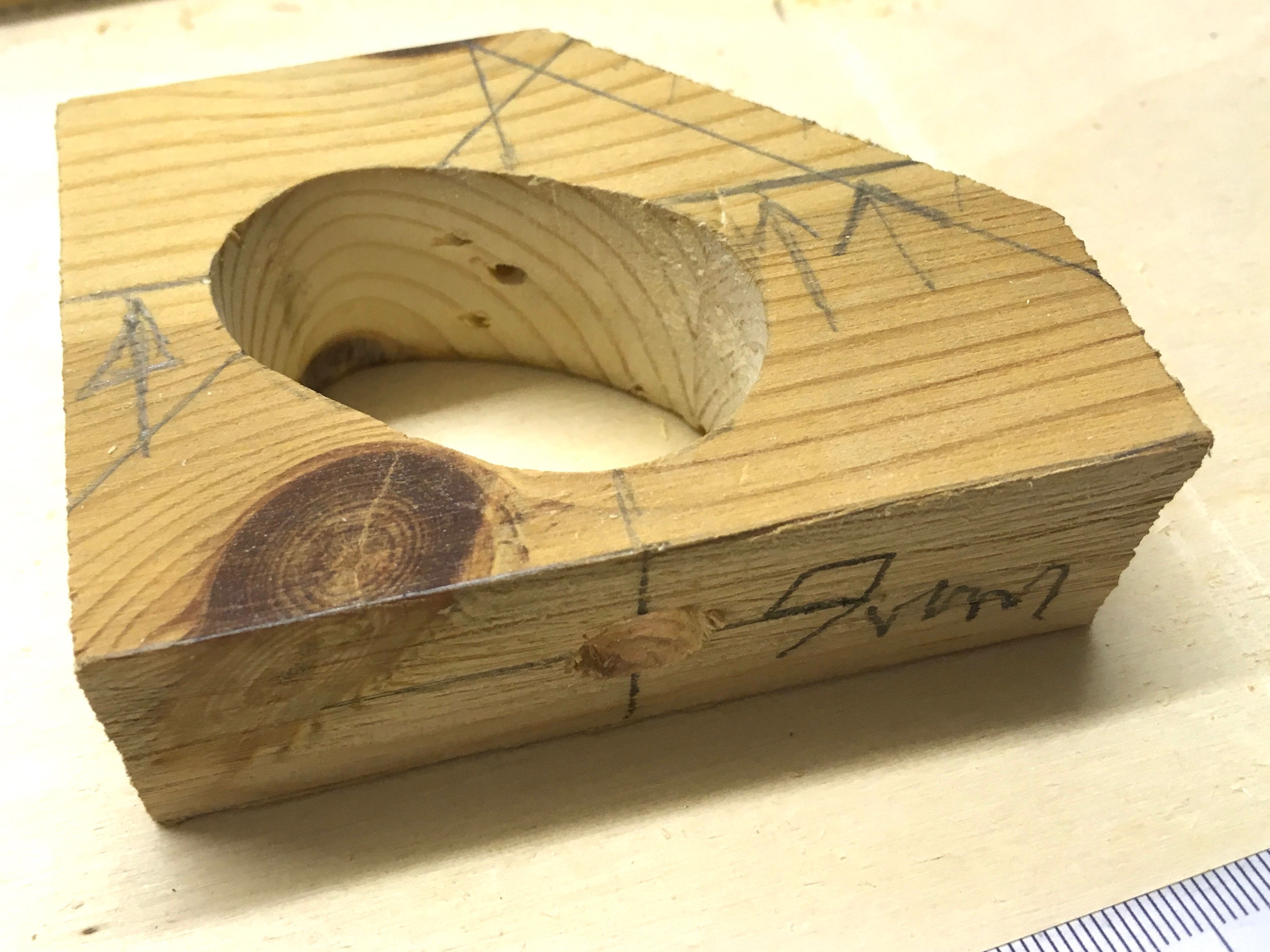
This clever donkey needs a hole chiselled in its head for the ears to move. For the neck hinge, mark the wood that needs cutting away using the cardboard templates to check what needs to be removed before sawing. To cut the arc shape, a sharp chisel is what’s required. Try fitting the ears to see that the hole is big enough for them to move freely.
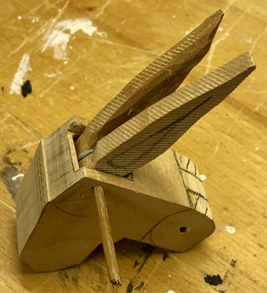
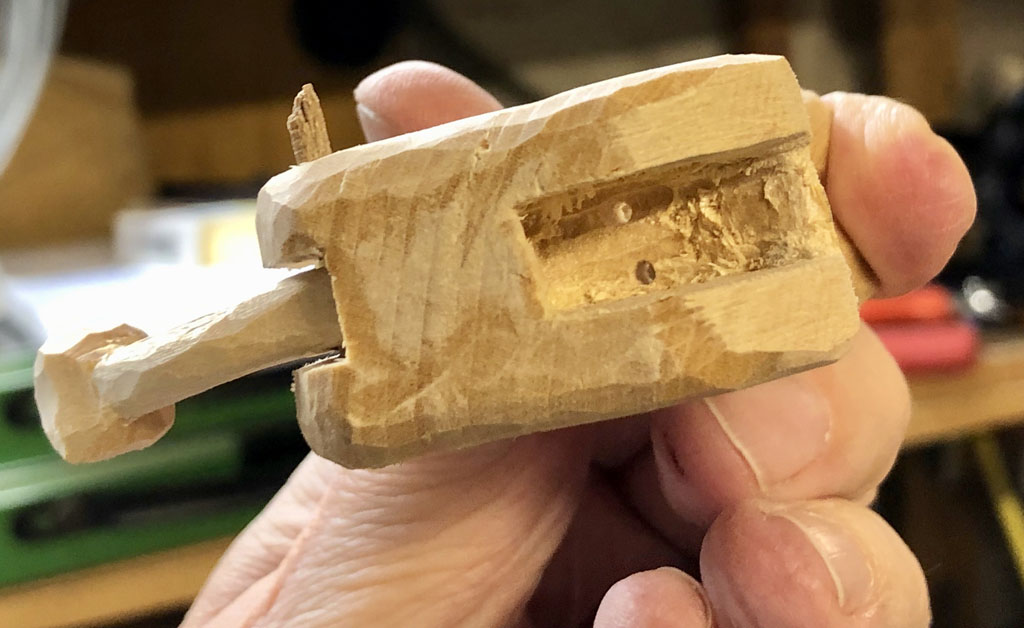
I left enough space for a small plastic washer between the ears to make sure that they can move separately. Roughly carved, head and ears look like this.
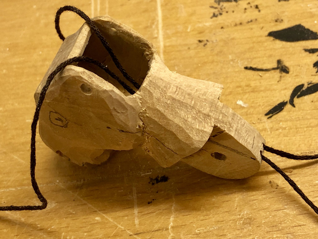
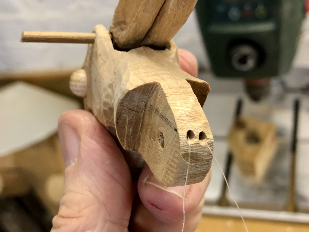
I used cord to waggle the ears and the tail. I tried cotton thread, but that caused too much friction. I tried fishing line, but that was too stiff when relying solely on gravity to pulle the ears down. I finally settled on thinner 1.5 kg nylon cord which is smooth and flexible enough for the job.
Here you can see how I drilled two holes along the neck, one for each ear. Note that routed like this, the cord which pulls the ears up will also pull the head up, when the ear has moved as far as it can.
Here are the thinner, smoother nylon cords, ready to thread through the body.
Now drill two holes in the body for a tight fit to hold the dowel to pivot the head and the tail. Note that it is best to drill the holes while the wood is still solid and the sides flat. That makes it easier to be precise and less likely that thin bits will break off. Then chisel out the space needed for the neck to rotate at the front and for the tail to rotate at the rear. Pencil markings on the outside show roughly how much space is needed for the movement.
Once there is enough space for the neck to move freely, drill two holes through the body for the ear pulls. One hole is enough for the tail.
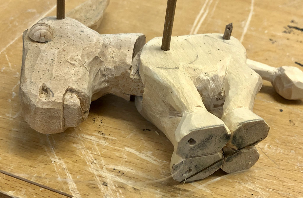
For the ear pulls, I fed the cords through the front hooves. For the tail pull there was enough space between the two rear hooves
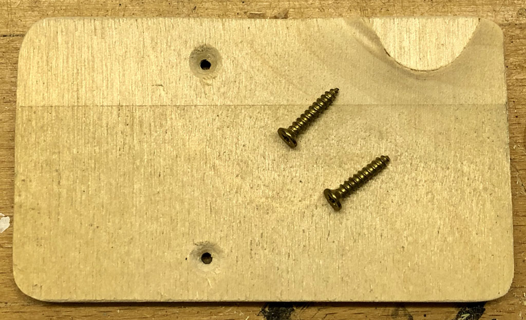
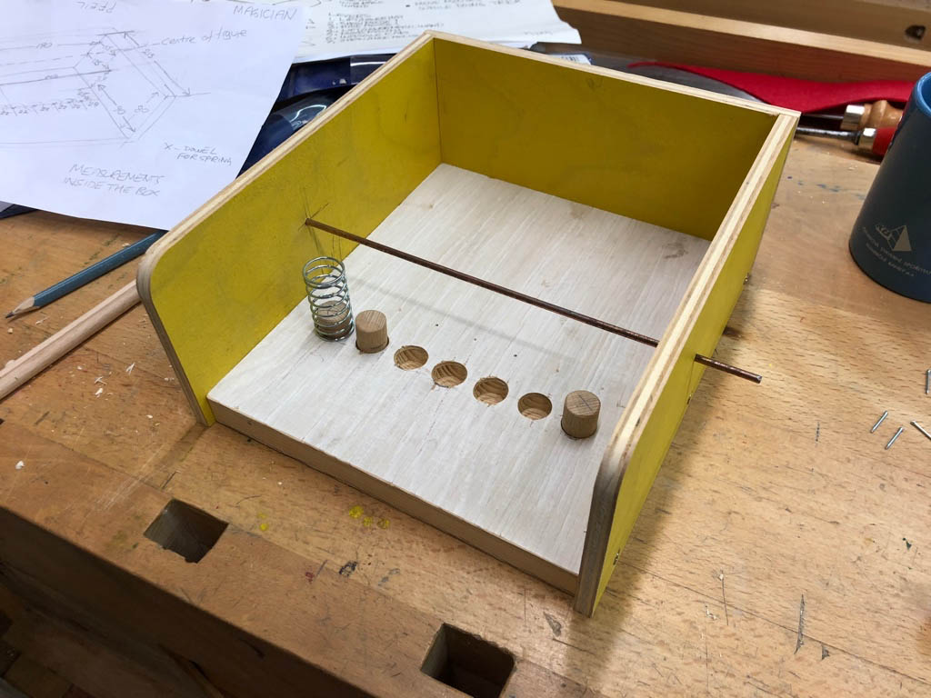
I recycled an old round wooden base for Goldesel to stand on, adding some smooth pieces of dowel to reduce the friction when the cord has to turn through 90 degrees. There are two holes at the front to connect the carrot to the two ear pulls and one hole at the rear to connect a coin to the tail pull.
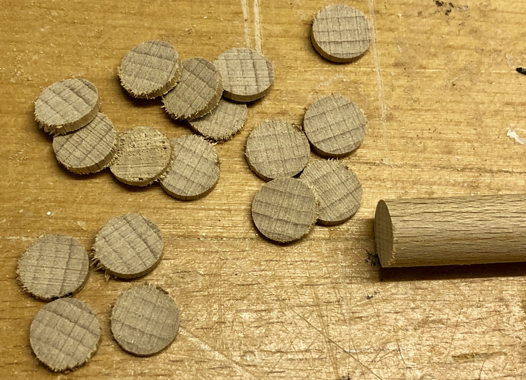
I’m afraid my gold ducats are only made from beechwood dowel with a lick of gold paint. Go for the real thing if you feel like it!
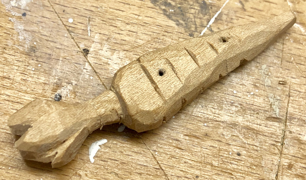
Carve a carrot and drill two holes in it, one for each ear pull.
We need a base for the carrot and the ducats.
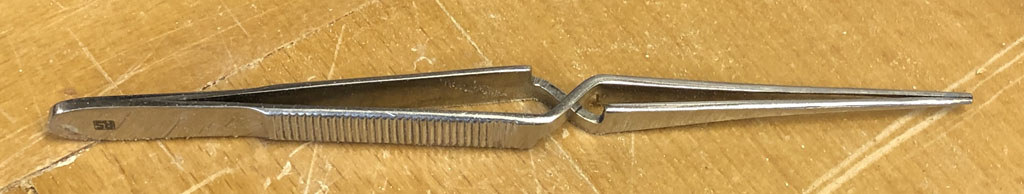
Now everything is ready to be assembled. Threading the fine cord can be quite testing and I found press-to-release tweezers quite handy to keep my frustration levels down.
Goldesel was an interesting experiment in using pull cords running inside a figure, like an inside out marionette. Unlike a thumb puppet it has no spring and relies on gravity to move ears, tail and head back to their starting positions. Before demonstrating, it is vital to practise your braying. The onomatopoeias for braying is “hee-haw” or “eeyore.” Curiously the National Geographic thinks that donkeys say “wee-snaw”. As a fan of Winnie the Poo, personally I go for eeyore.
Nativity scenes are an inseparable part of Christmas in the Czech Republic, and as the festive season approaches you will find them at almost every Christmas market. Nearly every Czech city or town has a Christmas tree in the main square with a nativity scene beneath the tree. Each nativity scene is original and unique. The story of baby Jesus, with a manger for a crib, is shown in many ways by artists and one artist in particular is responsible for perhaps the most elaborate nativity automata in Europe: Josef Probošt.
Probošt’s mechanical Christmas crib
Czech farmer and carpenter Josef Probošt lived in a small village called Třebechovice pod Orebem (current population 5700), about 120 km east of Prague in the Czech Republic. In 1999 his automata was declared a Czech national cultural monument, but work actually started in 1885, while Queen Victoria was still on the British throne.
It is thought that he initially made it for his wife, following the death of their 7 month old son. She liked it and he decided to enlarge it, bringing in another carver Josef Kapucián, and Josef Friml who was a “mill carpenter” and a specialist in the making of cog wheels and other mechanical parts made of wood. Probošt was a deeply religious man who held his work for an altar. His original, modest concept was of a religiously based nativity scene with the infant Christ, angels, stars, wise men and so on.
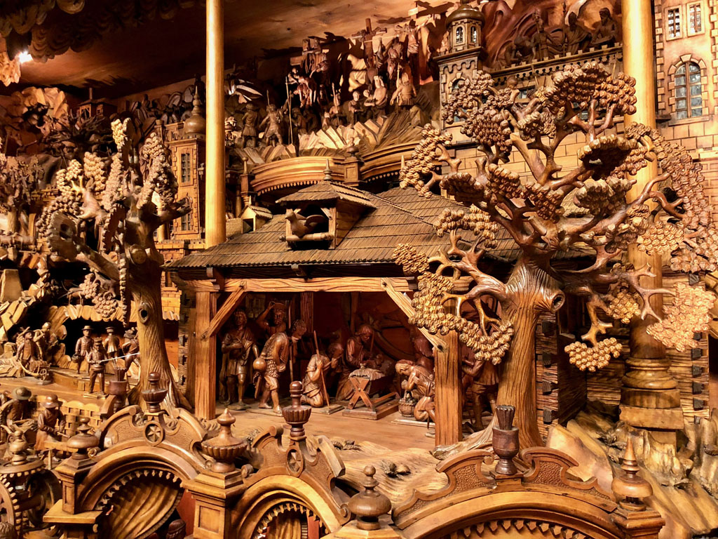
As it grew year for year, the concept grew with it to show all aspects of rural life in Bohemia at the beginning of the twentieth century including subjects such as mining, carpentry, weaving and farming, not forgetting the blacksmiths and the musicians. Local residents who visited Probošt to admire the nativity scene during its construction served as models for many of the characters depicted. Probošt himself can be seen as a carpenter and Kapucián as a wise old man. Probošt kept working on it for forty years until he died in 1926, leaving all of the farmwork to be done by his wife and daughter…
How does it work?
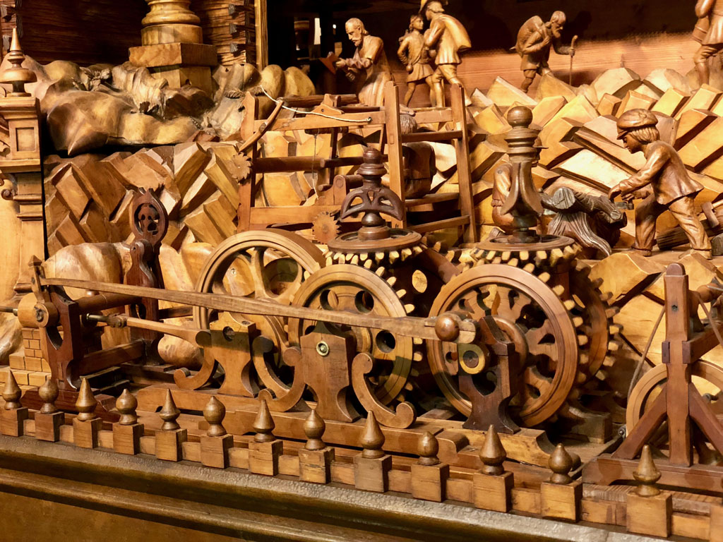
To make it work, there is a large wooden wheel around the back which could originally be turned by hand, activating the belt drives, shafts, cogs, cams, wooden chains etc. to bring all of the scenes to life. From 1935 a motor was used and since its extensive restoration a few years ago, an electronically controlled electric motor does the work, with laser beams monitoring its smooth operation.
It is 23 feet long and is made up of about 2 000 carved parts, including 373 individual figures, illustrating 51 crafts in the community with 120 figures which move in a procession around the scene on simple but obviously effective wooden conveyors.
Where can you see it?
It was first exhibited in 1906 at the Provincial Artisan Union in Chrast where it won a diploma and a gold medal. After Probošt’s death it was occasionally exhibited in various places in central Europe, even being shown at Expo 67 in Montreal where more than 8 million visitors saw it, including Queen Elizabeth II and in 1970 it was shown in London at the Ideal Home Show exhibition.
Since 1972, it can be seen in a small village called Třebechovice pod Orebem, which is presumably part of the Czech government’s attempt to entice tourists away from central Prague. You can drive there, or, from Prague you can take a train to a town called Hradec Králové and there you can change trains to cover the last 14 km to Třebechovice. From the station it is a short walk to the Museum of Christmas Cribs. The village has one small restaurant, Restaurace Na Roli serving traditional Czech meals.
It is fascinating to see how a vast automata could be built up by a man with a passion, helped by a couple of friends, using very rudimentary but very effective technology, over half a century before the Mechanical Model Museum in Covent Garden launched the new wave of automata building. Equally fascinating is to consider the trades and activities shown and to consider what their contemporary equivalents might look like, carved in lime wood of course.
The Czech Republic and Prague are well known for puppetry. In the days of the Austro-Hungarian empire, conventional theatres were obliged to perform in German, so small travelling companies of puppeteers who were allowed to perform in Czech could offer more than just entertainment for the children and even now, one hundred years after the end of that empire, puppet shows for adults are still to be found and seem to be much appreciated from the couple that I saw. Modern Prague also has a well-regarded film animation scene, resulting in a good supply of experts in puppet, armature & model making. Master craftsman Miroslav Trejtnar and his team have also taught hundreds of students how to make puppets at his Puppets in Prague workshops and when he announced a brand new “Mechanical Object Workshop”, I thought it’s time to pay Prague a visit.
Some of the Team
Miroslav (Mirek) Trejtnar graduated with high honours from the puppet design department of the Prague Academy of Performing Arts. He has trained with Institut UNIMA in Charleville – Mezieres in France. In 1989 he started the KID Company, designing and producing wooden puppets, toys and sculpture. Mirek’s art has been exhibited around the world, including at several UNIMA festivals. He has designed puppets for numerous productions, including “The Baroque Opera” by the Forman Brothers. He has also produced puppets for the Jiri Trnka animated film studio in Prague. Mirek has taught hundreds of students at Puppets in Prague workshops. He has also taught for the Academy of Performing Arts in Prague, St. Martin’s College of Design in London, New York University in Prague, Chapito Circus Academy in Lisbon, Portugal, and in Macao and Hong Kong.
Zdar Sorm worked for the Jirí Trnka animated film studio at Barrandov studio in Prague for 20 years, and is now a freelance designer of puppets for film animation and theatre, as well as a graphic and furniture designer. He is one of Prague’s leading experts in the technological designs for animated films.
Leah Gaffen is an American who has lived in the Czech Republic for over fifteen years. She founded the Puppets in Prague workshops with Mirek Trejtnar, and has worked with him as a producer for the course since then. She has also done production and translating work for the Prague Theatre Academy and numerous theatre education projects.
The Preparations
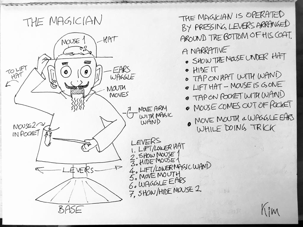
Drawing of suggested project for the Mechanical Models Workshop
To apply for a place, I sent a few details of things that I had made in the cellar. Once accepted, Mirek asked for an idea of what sort of mechanical model I would like to build, so I sent him a drawing, with a rough outline of what movements I’d like. We exchanged a couple of emails and he said, yes we can make that.
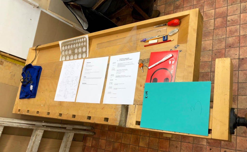
Mirek’s American wife, Leah Gaffen dealt with all of the organisation, booked accommodation, a puppet show just before the course started as well as an evening at the circus, sent a pocket map of Prague and even some tickets for Prague’s public transport system, which is great when you first arrive, confused by the unfamiliar surroundings. Add a schedule for the course and loads of tips about Prague and we were all set.
Via the social media page set up for the course I was pleased to see that three of the five students were repeat offenders, which is a very concrete statement about the previous workshops.
The course
The six-day course, 8 hours a day, with a day off in the middle, was basically in 4 parts:
workshop fundamentals about machines, tools and materials
various mechanisms to make things move
maquettes to test out the movements for your own project
building your own project
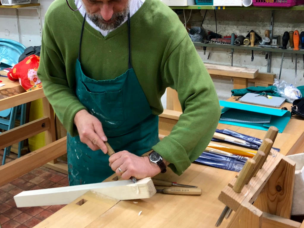
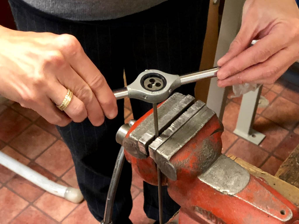
Fundamentals – photoessay
One tidy workbench per student ready to get started.
Types of material and their quality.
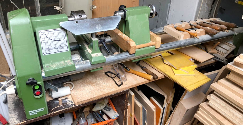
The lathe ready to turn some wooden wheels.
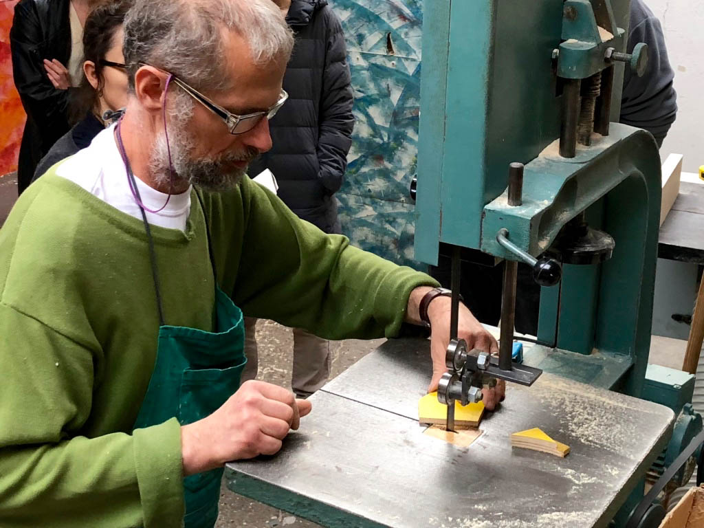
How to use a bandsaw properly.
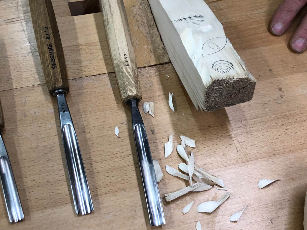
Chisels, sizes, shapes and their care.
Using a chisel.
Basics of brazing.
Tapping holes.
Cutting threads.
Mechanisms
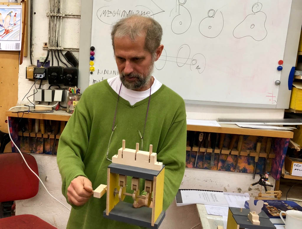
There is nothing better to understand a mechanism than to pick it up, make it work and inspect it from all angles. Mirek has a collection of mechanisms, some complete models from other artists and some basic mechanism, which he produced himself to illustrate how cams and levers can be used. This included Mirek’s own push along cyclist which is now included in the collection of the prestigious Victoria & Albert Museum in London.
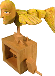
The “horse” and the “runner made by Peter Markey use fascinating mechanisms, I spent quite a while handling them to see exactly how the movement is produced.”Man and fly” by Robert Race uses a very simple mechanism but is very entertaining and shows that it doesn’t have to be complicated to be a success. Mirek’s own animated, carved face produce a really striking effect, just from a set of cams.
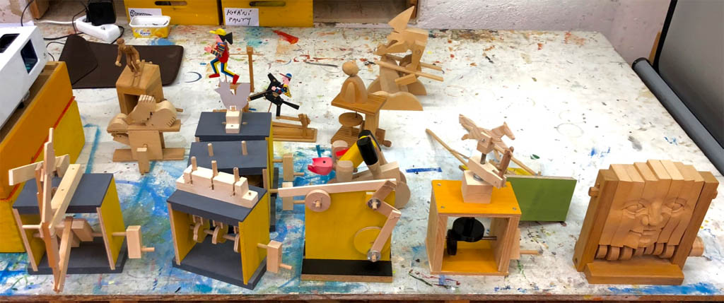
Mechanisms – photoessay
Examples, for inspiration and to understand the basic mechanisms.
Mechanisms, theory and practice.
Mirek with some of his small friends hanging around behind him and some online inspiration.
Mirek has made plenty of base kits so that we can try out the mechanisms ourselves.
Templates for three cams.
Three cams in action.
Making a maquette
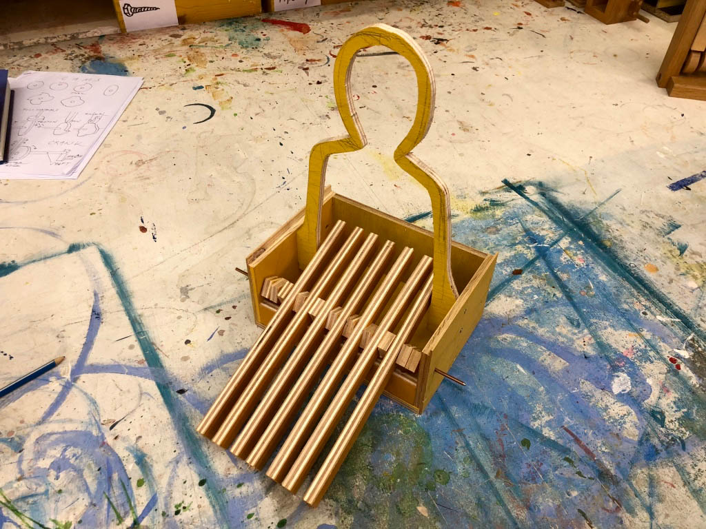
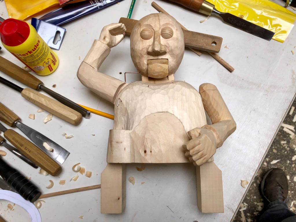
Having understood what mechanisms we could use in our own projects, we then moved on to trying our ideas out on a sort of working model or maquette. This means drawing your idea with enough detail that you can see how the moving parts move, which bits are hinged or which parts sit on an axle, or rest on a cam. This is a fascinating intermediate stage which shows whether your great idea can work or not. From this point on there was a flurry of activity as Mirek and Zdar and the team took our more detailed drawings and conjured up just enough of a starting point for us to work on the movements. In my case this meant a strange centimetre wide outline of my magician figure, standing on a box with seven levers, ready to do whatever I planned for the finished object.
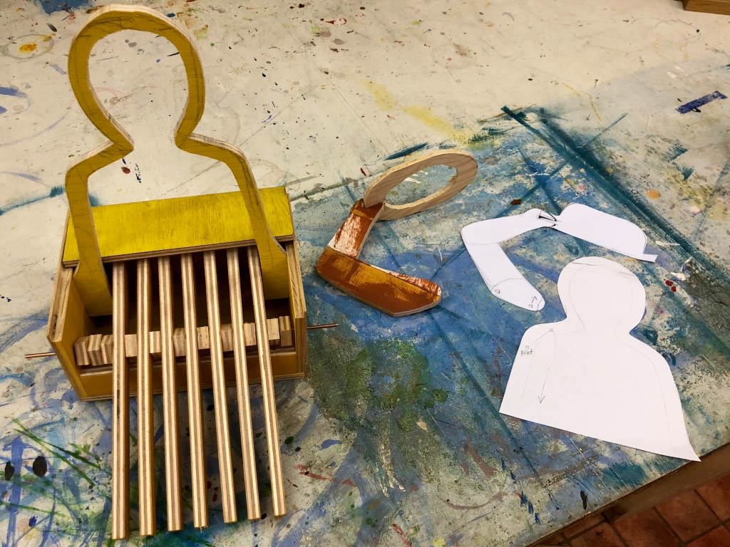
Once I had screwed together the parts which Zdar made for me, I could start the process of adding movement. This first means a real-size pencil drawing of something that moves like one of my magician’s arms. When you are satisfied, cut it out and try it on the maquette to see if it works. Is it the right size? Does it hinge in the right place? With a sharp pair of scissors this takes no time at all and a second or third attempt allows you to get it just right. When you are happy with the paper version, trace it onto a piece of plywood and cut it out on the bandsaw.
Making a maquette – photoessay
A “technical” drawing of your project.
The basic magician maquette, with seven levers and a simple outline of the figure.
Cut out parts in card, if they are OK, cut them in plywood.
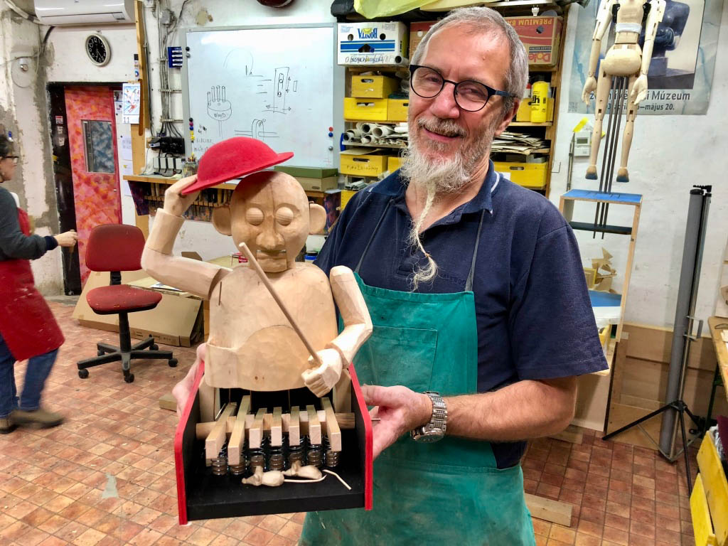
Two mechanisms already proven on the maquette, he can politely raise his hat and wave his magic wand..
After a day off to see the marvellous sights away from Prague, today we return to the workshop, eerily quiet at the start of the day.
The maquette is finished enough with its 7 movements to get ready for the real thing.
There’s always a magically replenished supply of nibbles to go with your tea.
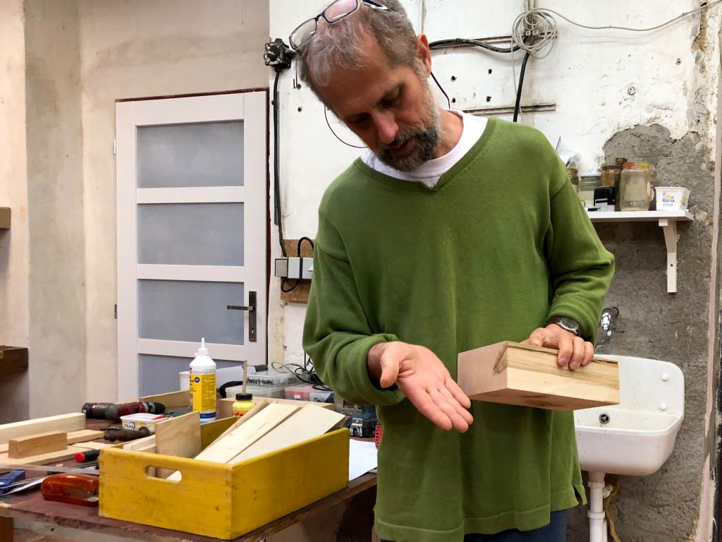
Making the real thing
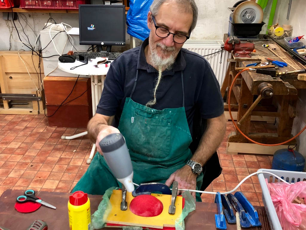
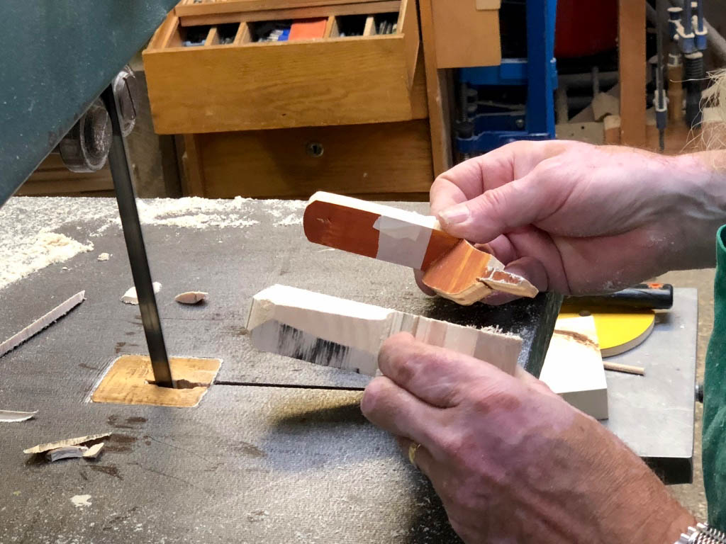
Having proved the principles on the maquette, it was now time to start on the real thing. To make the most of the time available I dismantled the maquette so that we could use the pieces as rough templates. For the real craftsmen it didn’t take too long to cut lime wood pieces roughly into shape, which I could then carve and prepare for assembly.
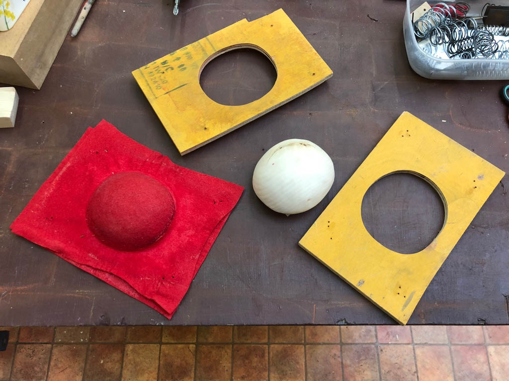
My magician also needed a hat and it was again wonderful to see how the experienced model makers go about that. Once we had decided that it didn’t need to be made of wood (I mean, who wears a wooden hat!), two layers of felt were soaked in diluted wood glue and clamped into an improvised hat mould. After drying out over night, I used a flat iron to smooth the rim and trimmed it to shape with a pair of scissors. Add a bit of wire reinforcement where the hand holds it and taraaa! A hat!
Making the real thing – photoessay
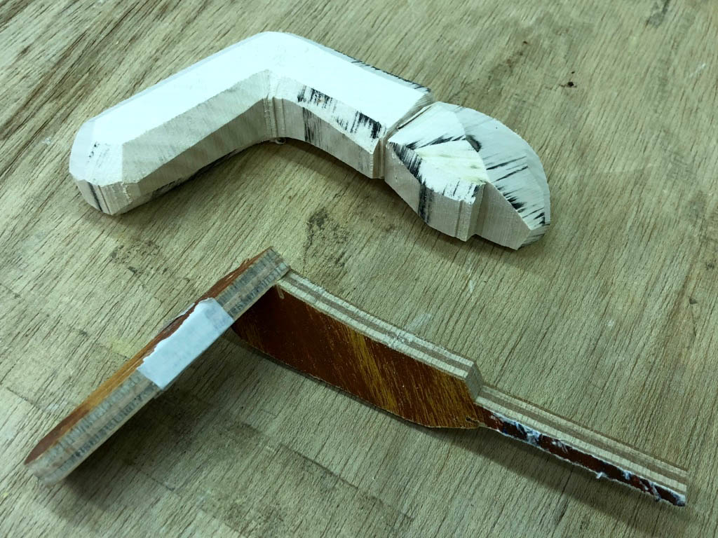
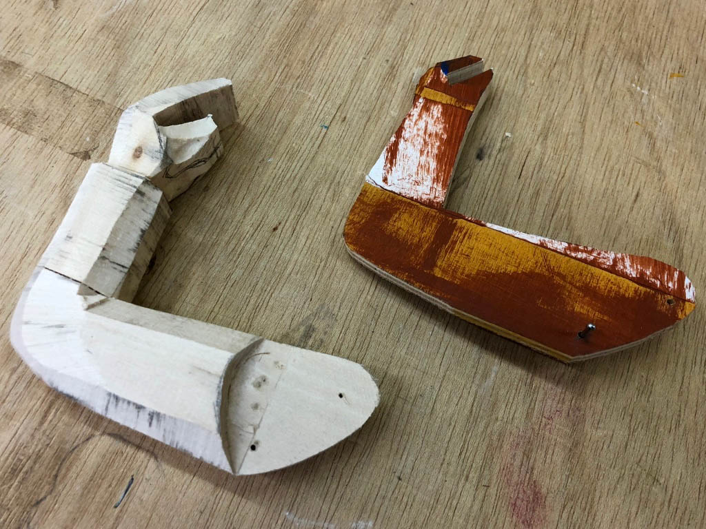
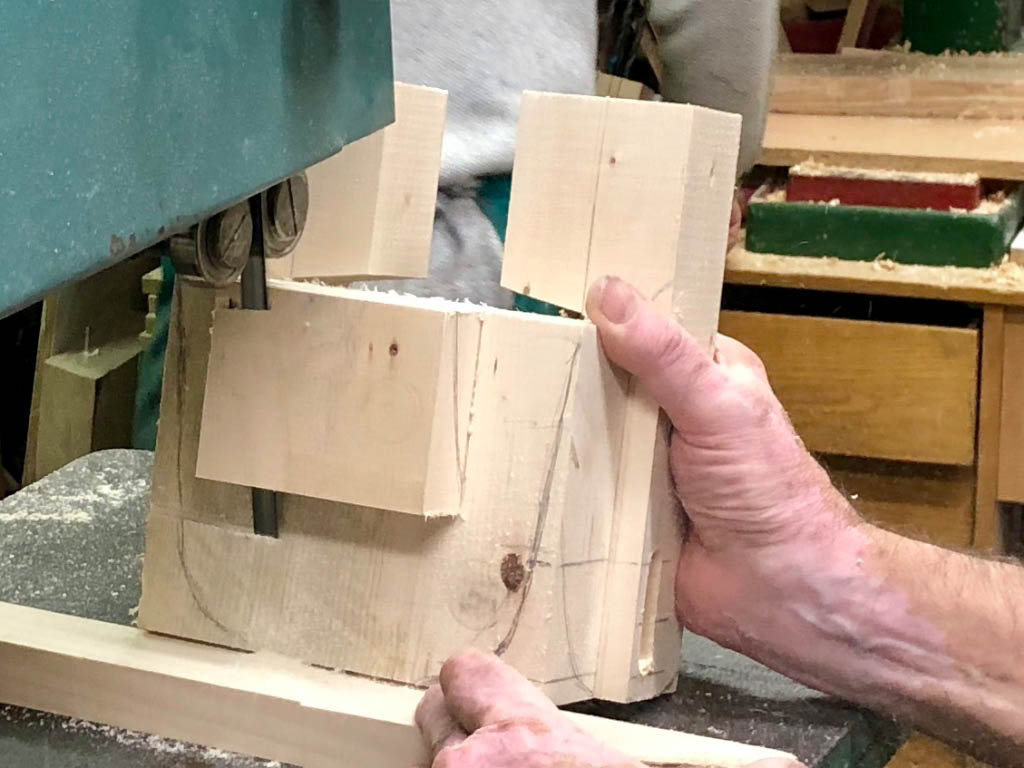
Cutting the left arm on the bandsaw from the marquette.
As finished from the bandsaw.
Same for the right arm.
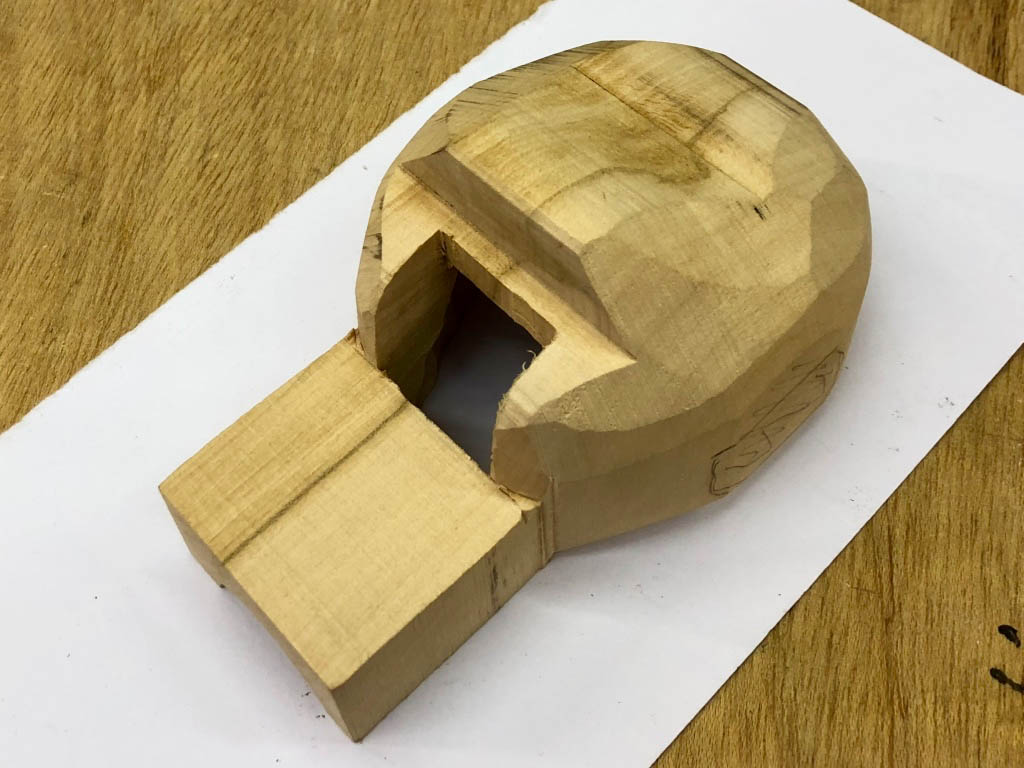
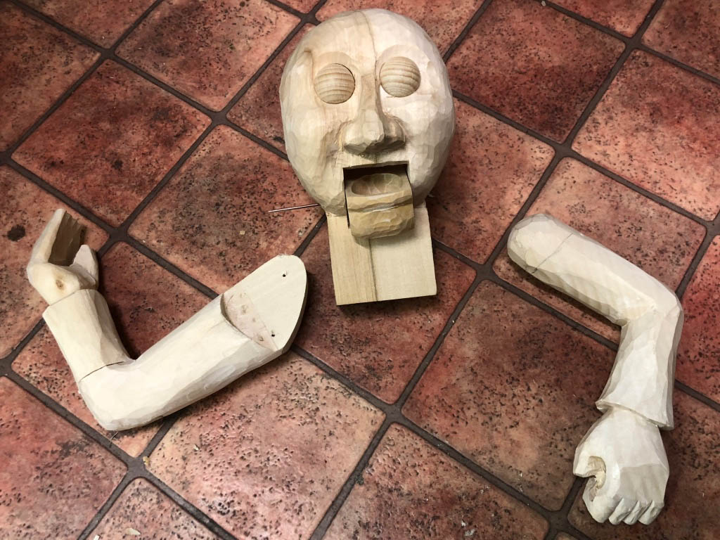
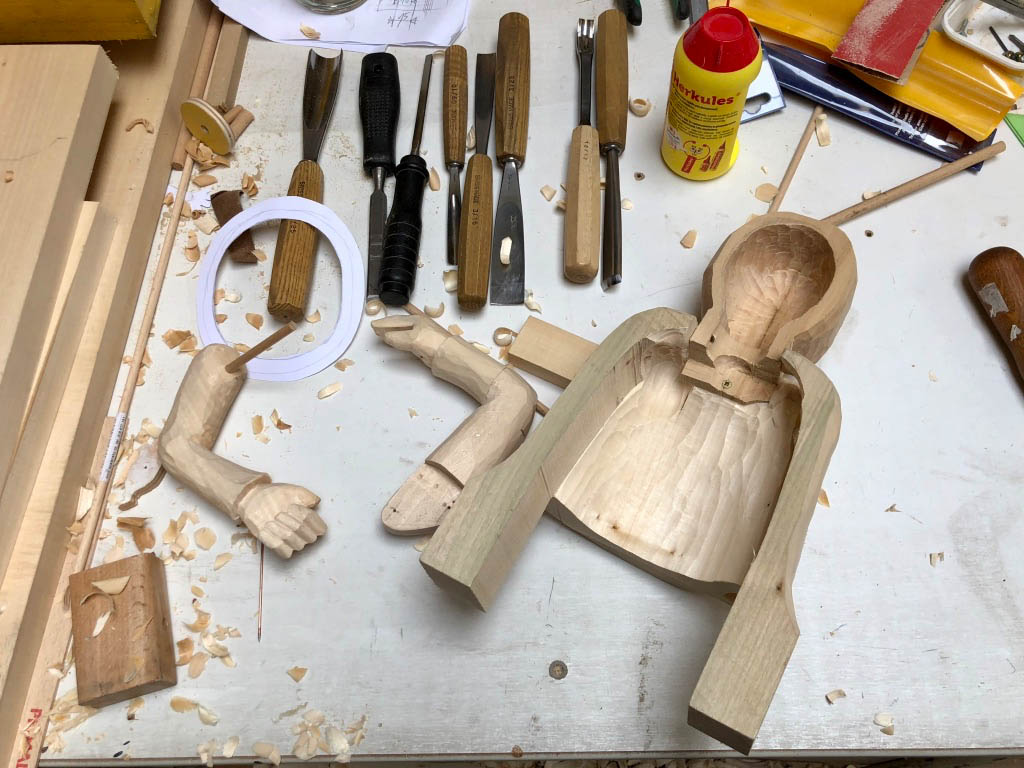
The head’s a bit more complicated…
After carving.
Zdar making a hat from two layers of felt soaked in glue.
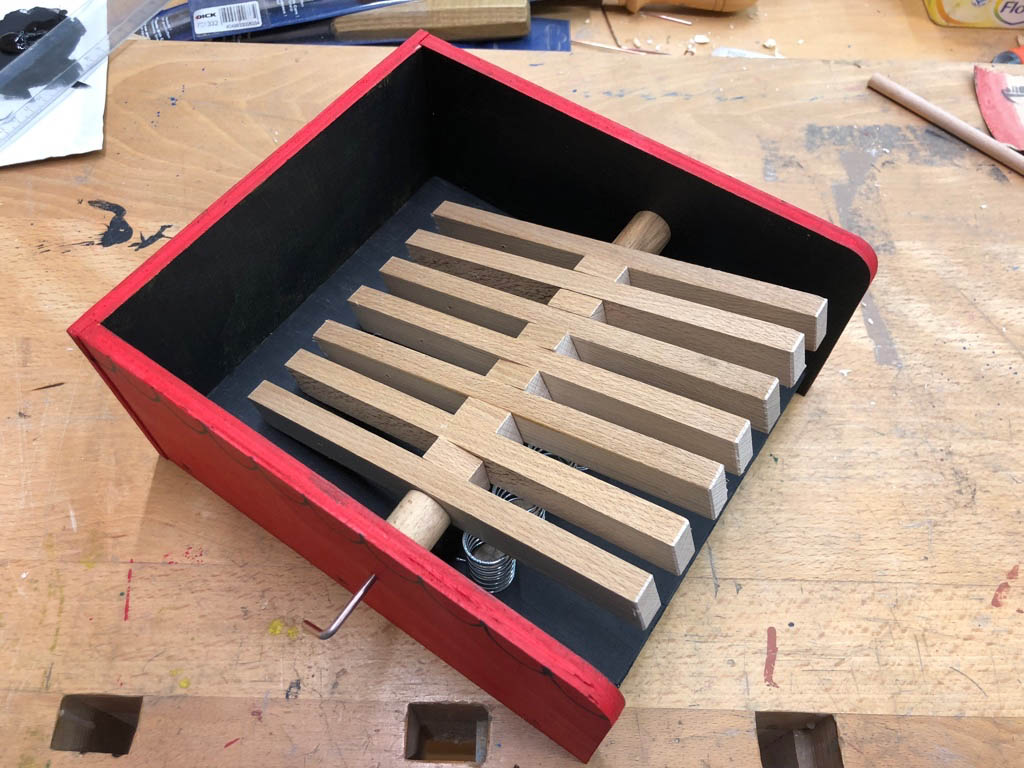
A new base in the right size, with holes in the right place.
New levers in nice wood.
Take the hat out of its mould and iron the rim flat.
Take the glued together blocked up body which dried overnight and trim it roughly to shape.
Try the head and body together.
Add the jaw.
Paint the assembled base.
Glue the head to the body and screw it into the base and start fitting the mechanisms as used in the maquette.
How did I like the course?
Although there wasn’t enough time to completely finish him, my magician was finished enough, and I was confident of completing it at home. I snaffled a few pieces of welding rod and some fishing line and set off for home, quite astonished about what we had achieved in one week. Once the magician was set up on my desk at home, I was very proud of him!
The other participants in the course came from a very diverse range of backgrounds and were very supportive. The atmosphere in the workshop was a very happy and positive experience. The course was held in English and sometimes some of the tutors struggled a bit to find just the right words. That didn’t actually matter at all, as actions speak so much louder than words and we all communicated just fine.
I also enjoyed seeing machines and tools in action which I don’t have at home. More or less the first thing that I did on returning home was to order a set of chisels and a few other bits & pieces which I had found particularly useful, to maintain the momentum and enthusiasm. The very deliberate process of making a maquette to quickly test out your ideas also really impressed me. In my days as a working engineer I would have called that “fast prototyping”. Seeing it used for mechanical models was a surprise for me, although it shouldn’t have been. That’s why you go on courses I suppose.
The accommodation was reasonably priced and very close by. The local high street was full of places to grab a bite of lunch. Leah organised an amazing cultural programme which for me included a puppet show, a music show, a modern circus, a trip to see the biggest mechanical Christmas crib on the planet and a very special visit to see one of Mirek’s old tutors. Fortunately I arrived a little early and had a chance to do some conventional sightseeing in advance. All in all I had a great time, learned a lot and now I understand why three out the five students had returned to Puppets in Prague after having attended a previous course.
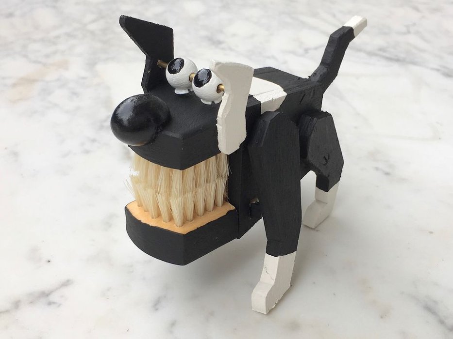
What can you make, that doesn’t have a fixed base, but can still do tricks? Man’s best friend of course! For simplicity’s sake, the design has to be reduced to just those things that make a dog a dog. If you like them, their essence is a shiny nose, appealing eyes, a wagging tail and a smile. If you don’t, it all comes down to the teeth. With four legs, one can be used to wag the tail and another to work the smile. The nicer the smile, the less there will be to worry about with the teeth.
What do you need?
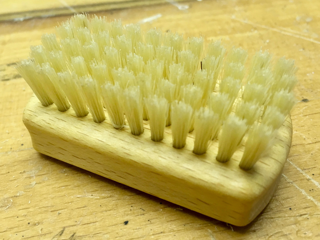
My dentist says that you must always brush your teeth for a nice smile, so a brush is vital.
Brush
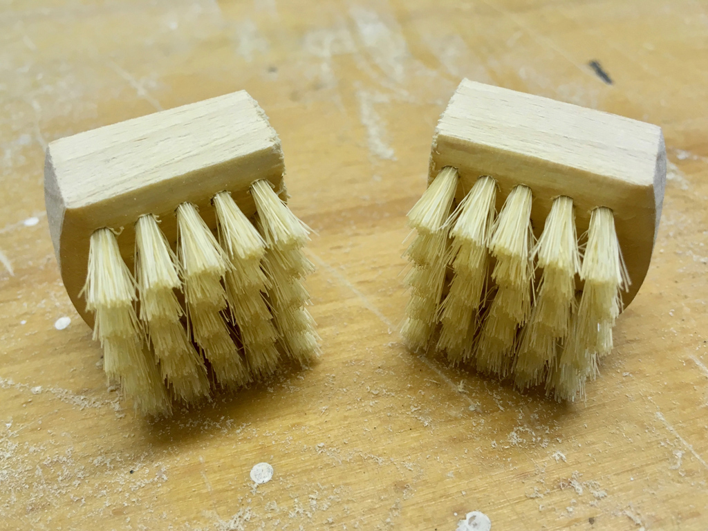
Sand the varnish off of the brush and cut it into two equal halves and an appealing smile is guaranteed and no one will be worried about the teeth!
An instant nice smile
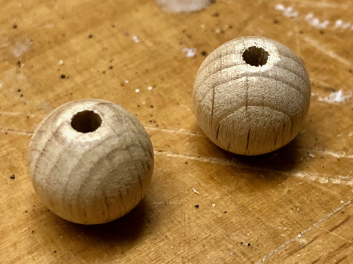
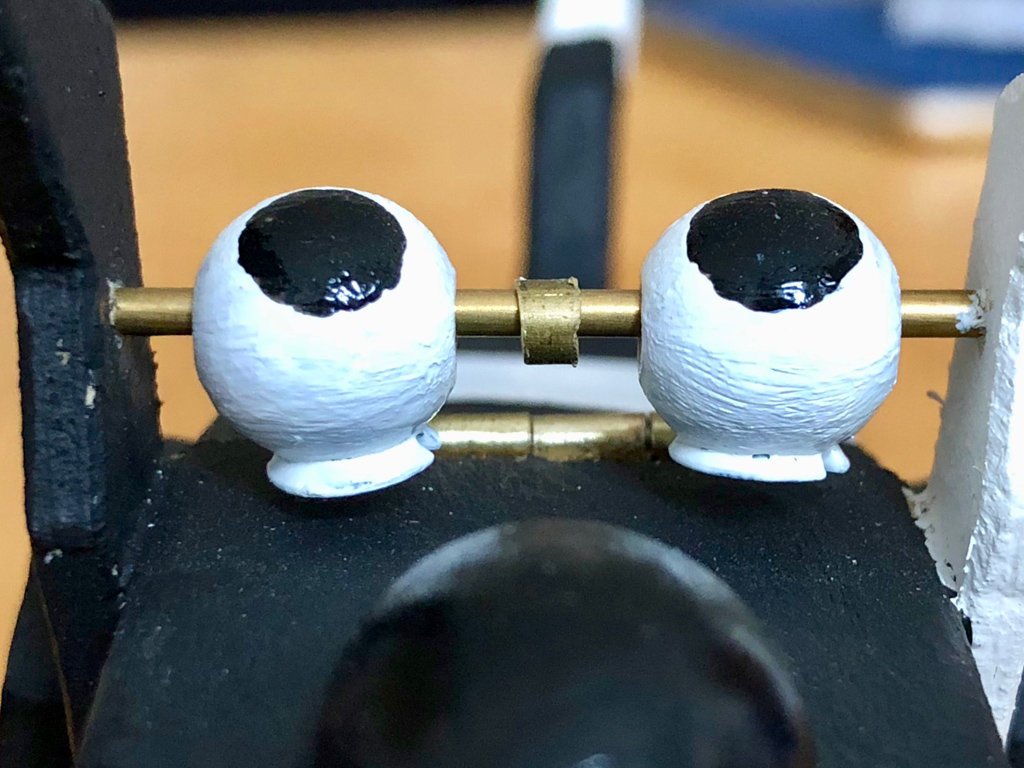
Eyeballs without brass screw heads
Bright eyes complement the perfect smile, and by gluing cut-off brass screw heads into two 10 mm beechwood balls, the painted eyes always look appealingly up at you, however you tilt the body. Intelligent eyes must never be too close together, so there is a small piece of brass tube between the eyes sliding on the brass rod glued between the ears. As the smile is so nice, no one notices the brass rod.
Bright eyes
Nose
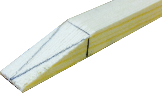
A 20 mm long beechwood egg just needs one quarter to be cut away so that it fits nicely in place and high gloss black paint gives it that healthy shine.
6 mm thick plywood serves very nicely for the dogsbody and its legs, cut with a scroll saw. The back legs are a little smaller than the front legs, which are hinged so that you can press them to work the dog’s tail and jaw.
A leg and its hinge, which is glued into the cutout marked on the leg
The tricky bit
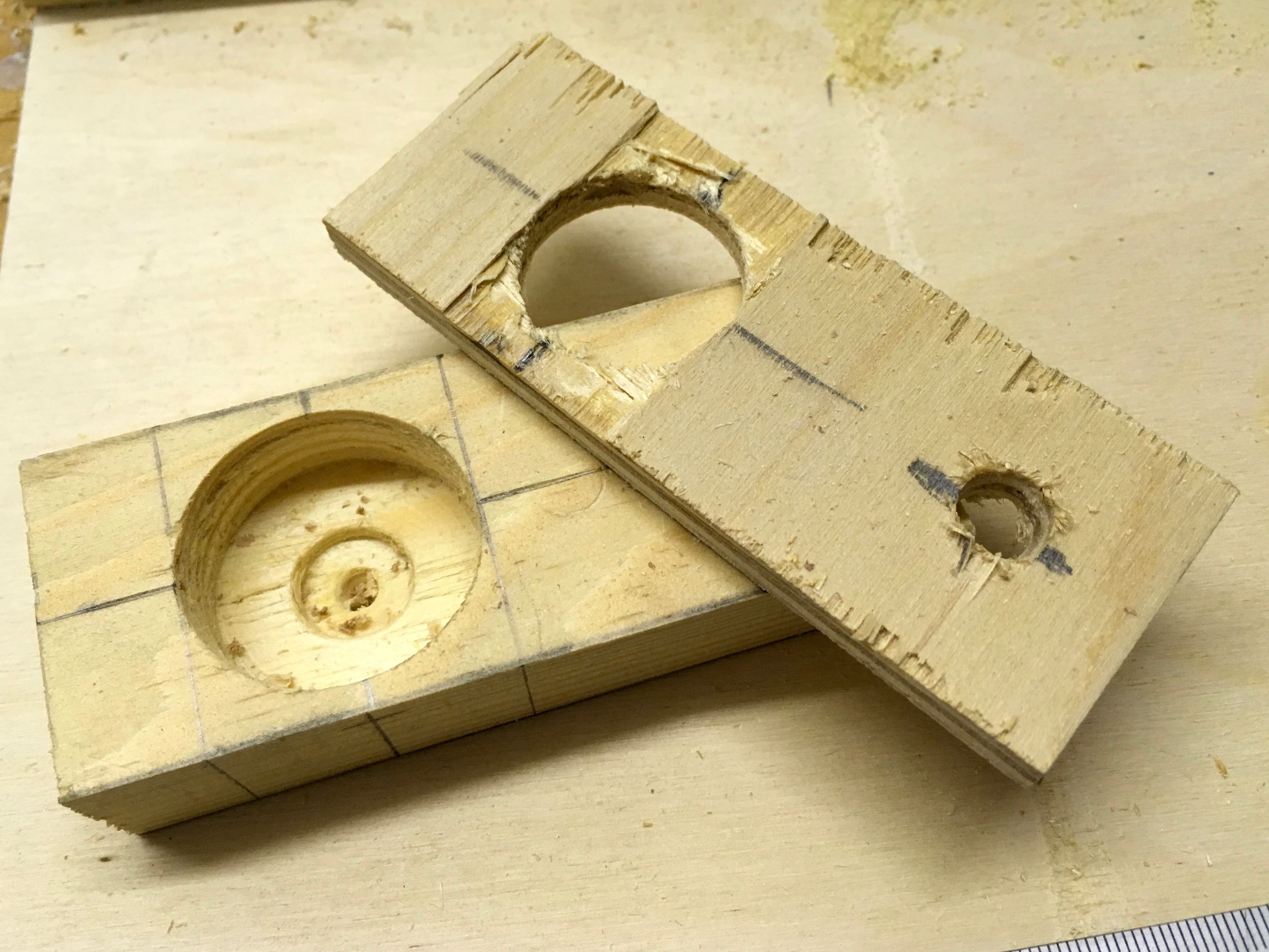
Each side has two rectangular cutouts. The top cutout is to hinge the leg, pivoted on a brass rod inserted from the front. The bottom cutout takes a crank, hinged on a brass rod inserted from the bottom. When you squeeze the dog’s leg against its body, the crank is pushed in, and its action then pushes the top jaw open via a sprung lever. Tricky huh? Here’s a picture and there’s a video underneath, showing it in action, which hopefully makes it easier to understand.
Mechanism to open the jaw
Pressing the crank from outside moves the lever, which then moves the jaw via the brass rod
Interesting things about brushes
One tuft held by a small piece of wire
Each tuft in a brush is just pushed in with exactly the right number of bristles to fit snugly. To remove a tuft just grab it with a pair of pliers and pull, just like a dentist! This is how I made space in the dog’s upper jaw for the slot needed to take the loop on the end of the brass rod.
The link to wag the tailThe return springs fitted
The end of my tale
I had to experiment a little to get the tail to wag nicely and to look OK when it’s not wagging, so its hinge is not exactly central. As you can see from the pictures not much is particularly square, but hey it’s a dog right, and here he is in his finished glory – Mechanical Mutt.
Mechanical Mutt – The video
Kim Booth – Bearded, bespectacled British bloke, born in the best bit of Birmingham, he blithely beavered to become a Bachelor in electronics, before boxing his bespoke belongings and boarding his bike to brave the borders, breaking out for beautiful Berlin. Belatedly, being both bilingual but bereft of business, he breezily became a broadband bandit, translating buckets of balderdash into Brummie British and by the by, builds bulldogs with bite.
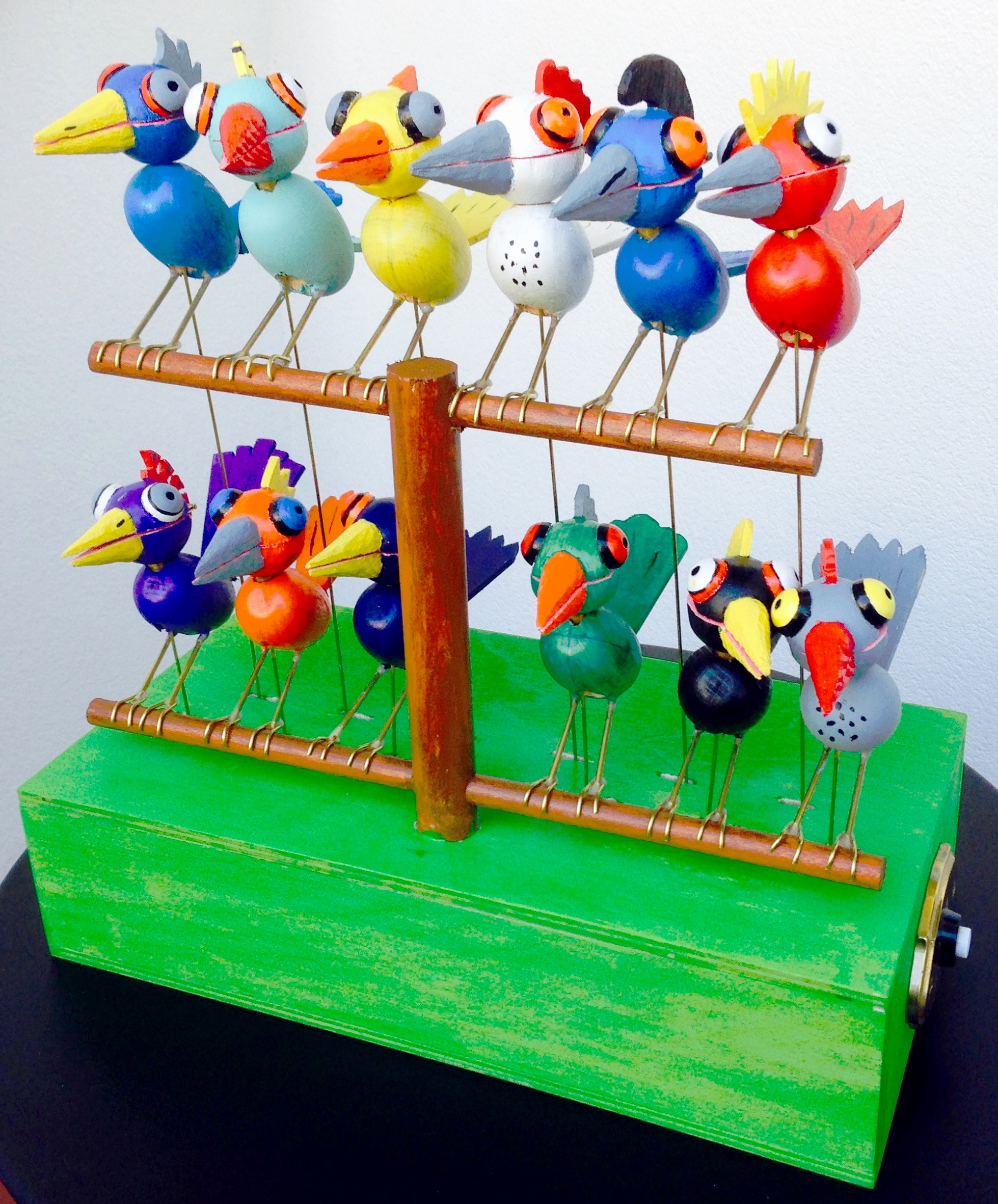
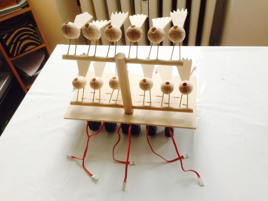
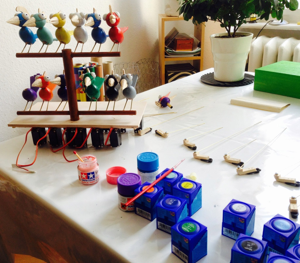
A clock with roots that occasionally hoots. The time it can tell without even a bell. Ask it nicely and it will tell you precisely, But if no one’s around it won’t make a sound. A dozen on their perch won’t leave you in the lurch, The assembled dawn chorus will sing something for us. To make time a pleasure – a real treasure – not just something to measure.
Why did I make this?
My aim was to make a clock that doesn’t look like a clock, and has no rotating hands to point to the hours and minutes. Cuckoo clocks came to mind and I really liked “bird’s tree” by the amazing Carlos Zapata, so birds seemed like a good start. Then I heard the BBC’s fantastic Tweet of the Day so I just had to make it.
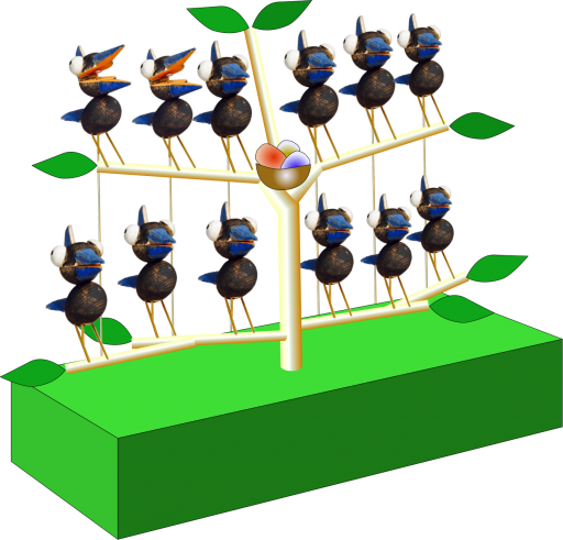
Moving from the initial concept to the final design
Original design for Twelve Tweeters
Things that are interactive are more interesting, so if no one is paying attention to the clock it shouldn’t do anything. Only when you really want to know what the time is should it do anything. Things that constantly move eventually just become part of the background and you don’t notice them any more. Not to mention the wear and tear on the mechanism.
Remembering Swiss cuckoo clocks, I thought it would be fun if the birds sang to tell us the time. Of course I had to break the Swiss cuckoo’s monopoly and open up the tree to all sorts of birds, so I chose a different bird for each of the twelve hours of the day. To tell whether it’s two in the morning or two in the afternoon, you just have to turn around and look out of the window.
Simple lever on the servo pushes/pulls the brass rod in this prototype.
For the minutes, the birds had to do more than just sing and more than one servo motor per bird was too complicated so, after experimenting with a prototype, the idea of a two-stage movement popped up. Push a brass rod half way and the bird’s beak opens. Push the rod all of the way and its head lifts up away from its body, apparently stretching its neck.
So now, when you push the button to ask the time, the birds first stretch their necks to show the number of hours from 1 to 12. For example, if it’s 3 o’clock, 3 birds will stretch up. The second part then follows, where each bird is responsible for 5 minutes, so for example, if five birds open their beaks and the fifth bird sings that means twenty-five past the hour.
For the ornithologists, each bird has its own voice 1 – blackbird, 2 – bee-eater, 3- chaffinch, 4 – goldfinch, 5 – skylark, 6 – duck, 7 – greenfinch, 8 – great tit, 9 – mistle thrush, 10 – ortolan, 11- marsh warbler, 12 – nightingale.
For more drama, a light shines on the birds perched on their tree as soon as you push the button. This stays on for half a minute or so after a bird has sung the time and a “dawn chorus”, recorded by someone early in the morning in an English forest, then plays quietly in the background for a while.
In the end I also succumbed to tradition and allowed the cuckoo to briefly show off on every full hour. When we have visitors, this inevitably tickles their curiosity and is an invitation to push the button and see what happens.
A short video showing Twelve Tweeters in action
Materials for the birds
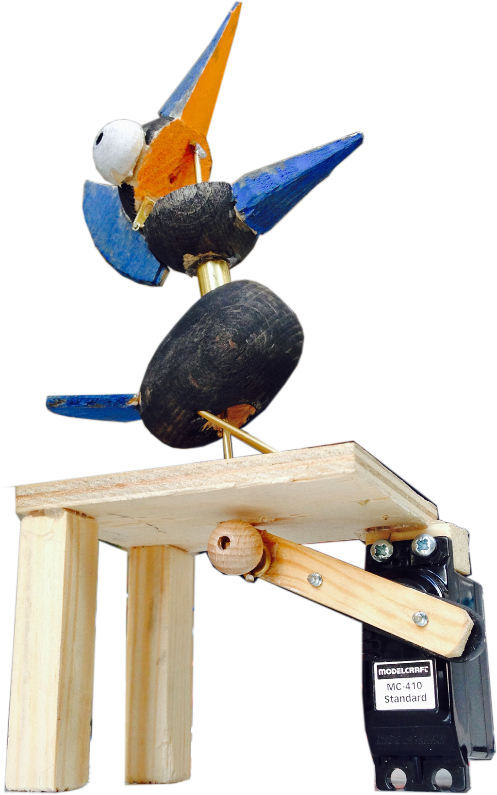
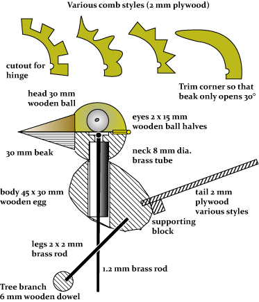
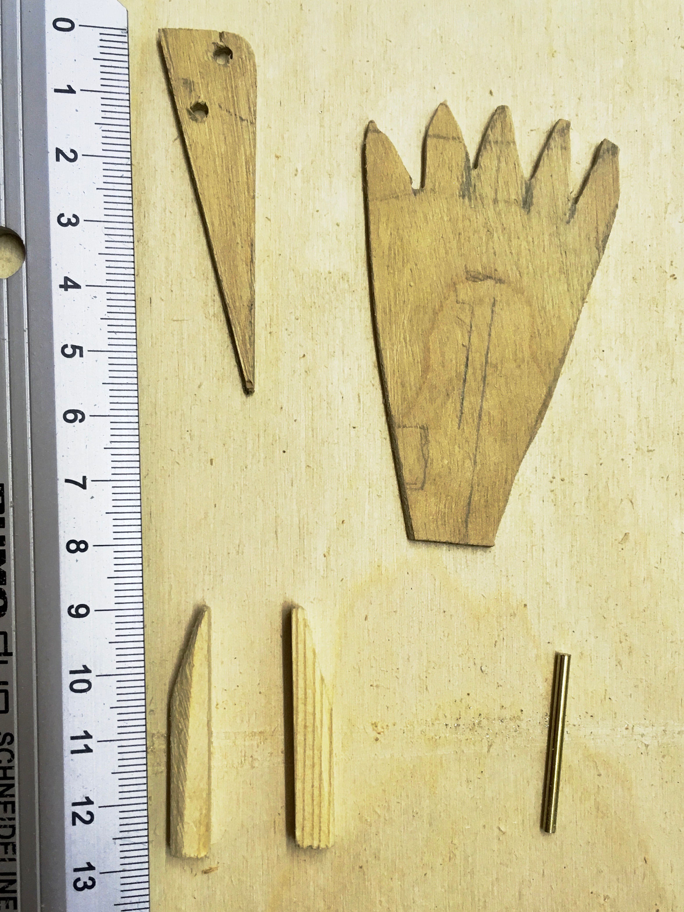
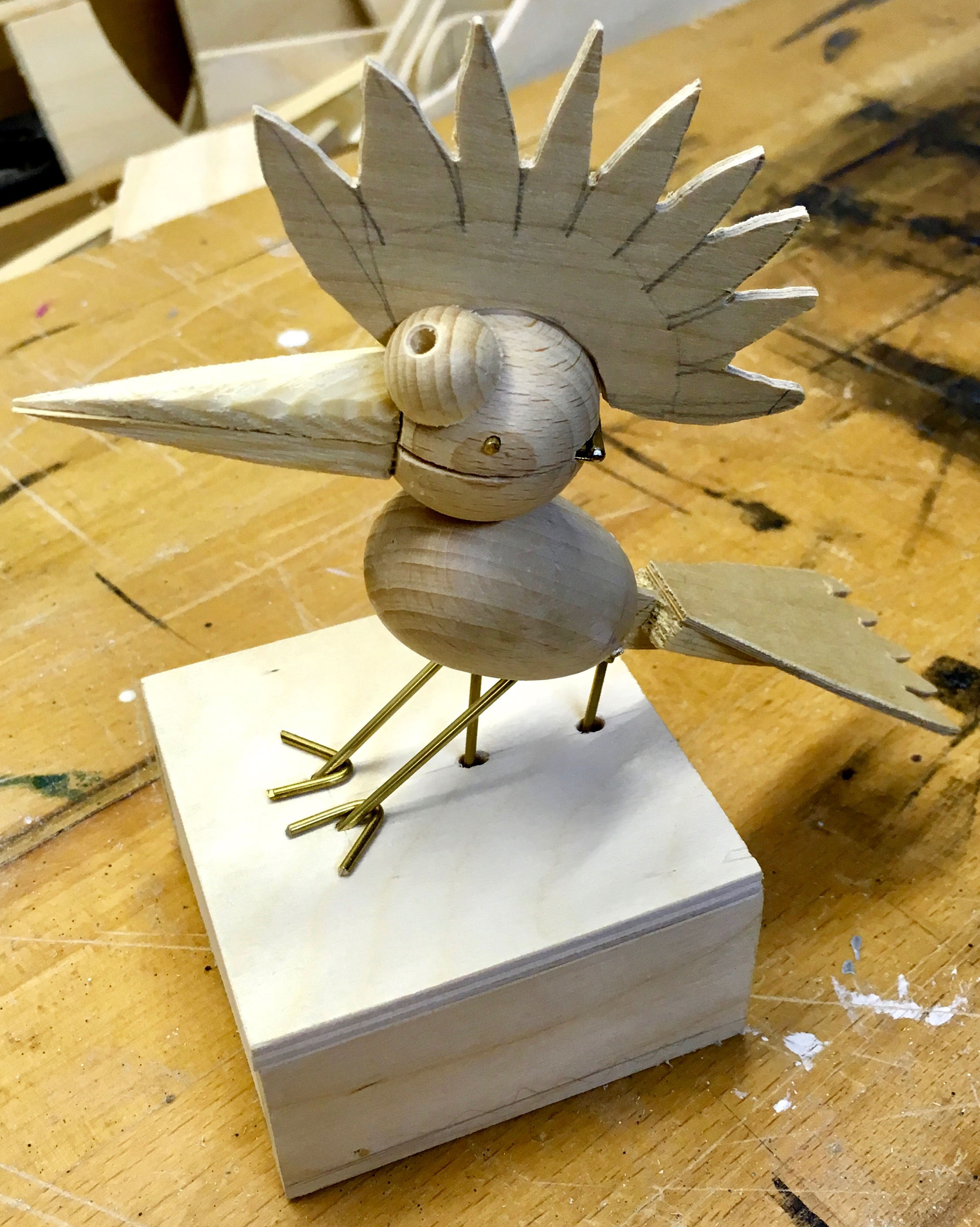
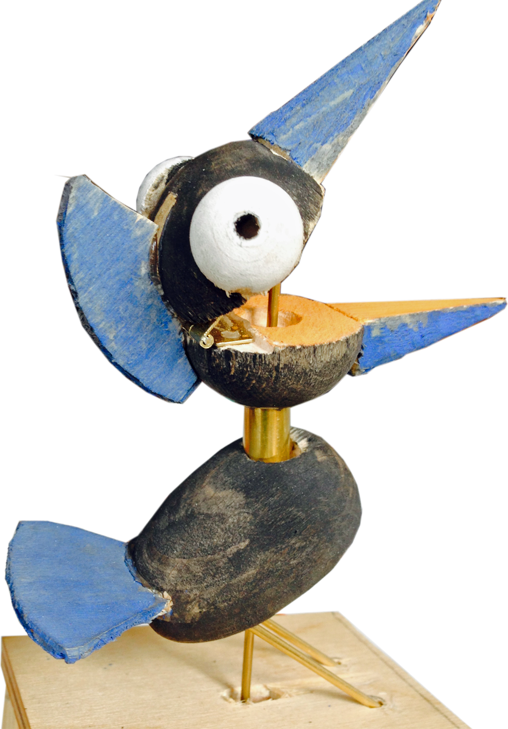
Anatomy of a tweeter
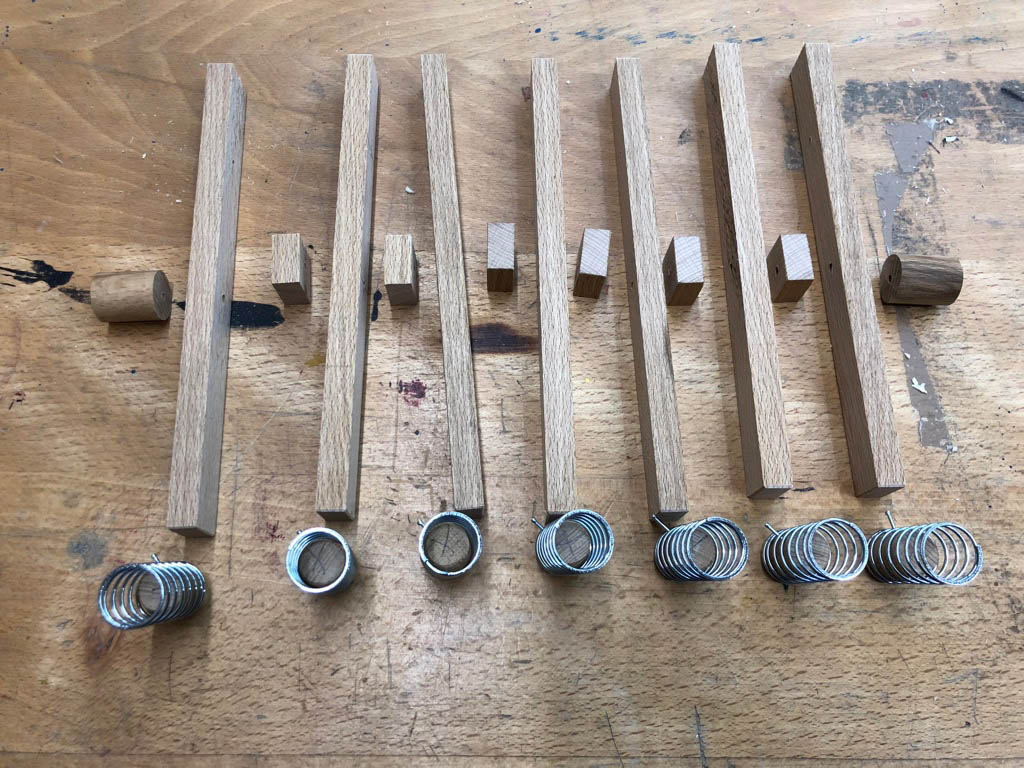
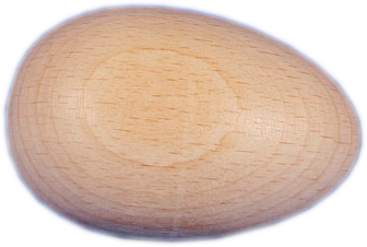
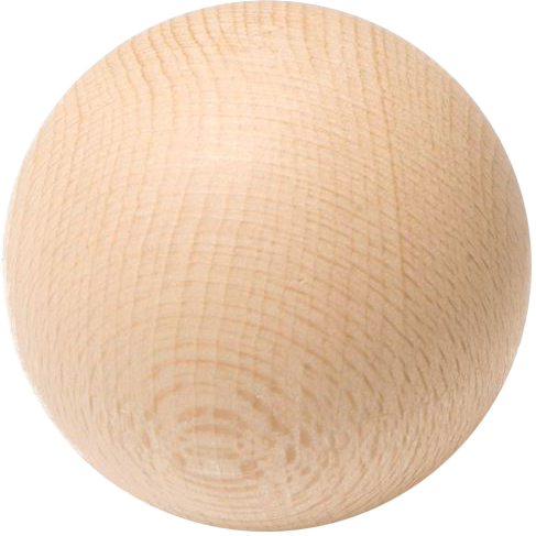
A beech egg, from which a bird will hatch
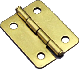
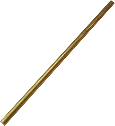
Everyone knows that birds hatch from eggs, so for each bird, I used one 45 x 30 mm egg for its body, one 30 mm ball for its head, two 15 mm ball halves for its eyes, 13 x 10 mm wooden strip to cut its beak, 8 mm brass tube for an extensible neck, a small free-moving hinge, 2 mm plywood for the comb, 2 mm brass rod for the bird’s legs and feet and 1.2 mm brass rod to connect to the servo arm.
Precisely drilling beech eggs and balls is tricky and although I made some jigs to hold them in a fixed position and drilled pilot holes, each of the 12 birds is slightly different, just like in nature. It wasn’t practical to screw or nail the hinges so I used fast-setting, two-component epoxy resin adhesive instead, taking care not to gum up the mechanism so that the beak still moves easily. The 1.2 mm brass rod is used to push the beak open until it reaches 45°(ish) and is restrained by the comb when the whole head will move up, exposing the brass neck which is fixed to the bird’s head but not to its body.
Making the birds move
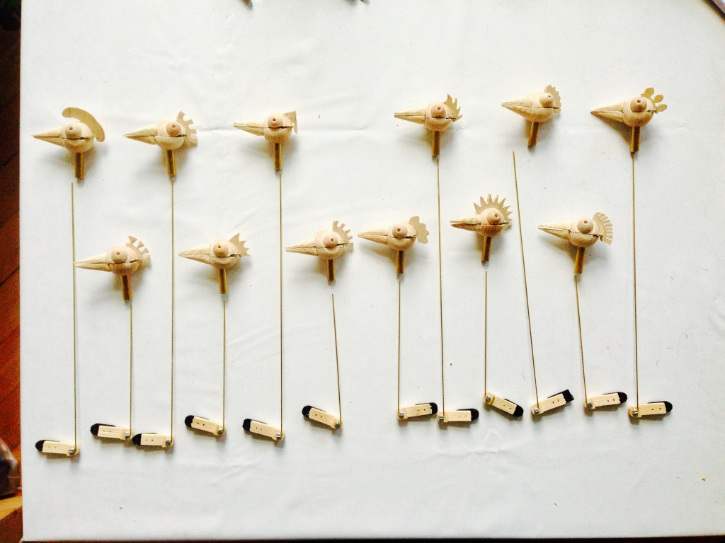
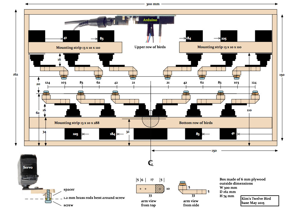
12 servo motors with wooden arms to push a brass rod up and bring the birds to life
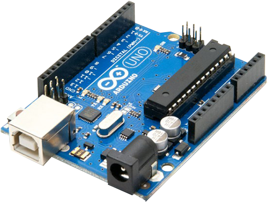
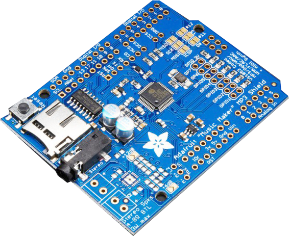
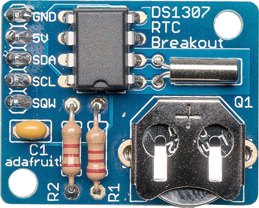
Previous generations would have used clockwork I suppose, but the flexibility of being able to programme the movements and sounds electronically is ideal when you are feeling your way with no exact plan. That’s why the base hides 12 cheap and cheerful servo motors which turn through an angle set by an Arduino Uno computer. I collected the bird tweets wherever I could find them on the Internet and they are kept in a micro SD card, which is read by a Music Maker shield and this is what drives the loudspeaker. A real-time clock board then tells the Arduino what time it is. When I got fed up of having to reprogram the Arduino from my laptop for summer time and then for winter time, I added a new button on the back which sets the time to 12 o’clock when pressed.
Ready to paint
It’s hard to say how much time you spend on a project like this. It takes a while to settle on an idea and then try a quick prototype to see if it does what you intended. I suppose once you start to make 12 of everything, that’s when the “work” starts. Maybe I then needed a week to make the parts and assemble everything.
The brass rods moved by the servo motors to bring the birds to life
Twelve headless birds waiting for feathers
Something like this is never quite finished. Once I had painted it and put it all together I found that having a button on the side meant that the whole thing slides around when you push it. After I while, I moved the button to the top and that problem was fixed. Then I put it onto a shelf at the dark end of the room and each performance required the lights in the room to be turned up. I made a quick trip to get some LED strips, added a new socket to the back and a small power circuit and now everything is brightly lit as required.
Now I am content and every time I hear a cuckoo in the distance, I think, is it that time already?
Kim Booth – Bearded, bespectacled British bloke, born in the best bit of Birmingham, he blithely beavered to become a Bachelor in electronics, before boxing his bespoke belongings and boarding his bike to brave the borders, breaking out for beautiful Berlin. Belatedly, being both bilingual but bereft of business, he breezily became a broadband bandit, translating buckets of balderdash into Brummie British and by the by, builds bright beechwood birds.
Meandering around Nantes, you will notice a painted pea-green line snaking along the pavement, zipping up unexpected staircases, sneaking along backstreet alleys and prancing with purpose across cafe pavement terraces. This, ingeniously, is Le Voyage à Nantes(www.levoyageanantes.fr), an urban art trail that leads curious visitors to dozens of works of art – sculptures, contemporary art installations, stunning viewpoints, architectural works – all over the city. Many – such as sky-rise bar Le Nid or the slide built into the 15th-century ramparts of Château des Ducs de Bretagne – are amusingly playful and interactive. The trail is 12km long, but can be traced in sections too. Pick up a city map, marked with the trail, at the tourist office or simply follow the green line and see where it takes you.
Flights
Transavia flights on Thursdays & Sundays only. Web site
Les Machines de l’île is a totally unprecedented project. A product of François Delaroziere and Pierre Orefice’s collective imagination, it is the only place where you’ll find Jules Verne’s “Invented Worlds,” the mechanical universe of Leonardo da Vinci, and Nantes’ industrial history, all on the exceptional site of the city’s former shipyards.
Some strange machines came to populate the Île de Nantes. After the Grand éléphant, this is now the turn of a Manta Ray, a Sea Snake and of all kinds of incredible boats to take possession of the banks of the Loire River in the Carrousel des Mondes Marins. These uncommon machines were born from the hands of the constructors of the company La Machine and came to life in between those of Les Machines de l’île before the public’s eyes. Their backwards and forwards between the building workshop and the Galerie des Machines give impetus to the movement at the heart of the former Dubigeon warehouses. They convey a mysterious reality to this island just like the time when vessels were launched there for all the trips of the world.
17.8 km https://en.eurovelo6-france.com/etapes/la-loire-a-velo-nantes-le-pellerin
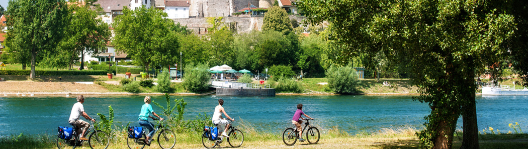
Contemporary art features large along the Loire’s long estuary and this stage shared by the Loire à Vélo and Velodyssey cyles routes. The installations are startling, set in unusual locations. They offer joyous surprises close to the city of Nantes.
DÉTOURS DE LOIRE
9h30-13h & 15h30-19h Monday to Saturday / 9h30-12h30 & 18h-19h Sunday and bank holidays
Classic bike for a half day : adults 10€ / Children 9€
123 stations and 1230 bikes are available in a wider area around the city center
For your short trips: Bicloo, self-service bike (the first half hour free). After subscription (on site or terminals) valid for 1 day,3days, or one year, you take your Bicloo and check it back in the stations available in the city center.
Open 7j / 7 and 24 hours a day, bicloo is a real complementary(additional) means of transportation in the bus, in the Navibus, in the stations and in the tram.
PRICE
Subscription from 1 to 3 days: 2 – 5 euros
The first half an hour : free
Then add : 0,50€ additional half an hour / 1€ : The extra half an hour / 2€ : additional half an hour
Further information at Maison Bicloo (6 rue Léon Maître) and Bicloo mobile application
The city of Nantes is only 50km from the Atlantic Ocean, making a coastal day trip a must.
Pack your bucket and spade for the classic seaside town of Le Croisic (population 4036), a pretty, half-timbered fishing harbour where shrimps, lobsters, crabs, scallops and sea bass are sailed into shore and unloaded. Talking of fish, the town’s aquarium is well worth visiting. Trains head to Le Croisic (€16.80, 1½ hours) from Nantes.
Along the way, it’s worth stopping at St-Nazaire (population 68,513; €12.30, 45 minutes), where cruise ships – including the Queen Mary II – are built.
Also along this stretch of coast is the glamorous belle époque resort of La Baule (population 15,456; €15, one hour), boasting an enormous beach. Gare de Nantes TGV8917 “Le Croisic” 47 Min. to Gare de Pornichet.
Nantes is a very good railway hub and there are trains going to interesting and attractive towns in almost every point of the compass. Eastwards up the Loire alley you could visit either Angers or Saumur. That chateau at Saumur is one of the most picturesque and was, indirectly the model for Sleeping Beauty’s castle. Southeast of Nantes you could visit Clisson or continue southwards to La Rochelle. There is a regular service southwestwards to the pretty little port of Pornic. Another line heads westwards along the northern side of the Loire estuary goes to Le Croissic, another picturesque fishing port, and passes through the traditional seaside resort of La Baule. Going northwest you can get to Vannes, an attractie town from where you an take a boat trip on the Gulf of Morbihan. To get there you may hae to change at Redon which is worth spending an hour or two, particularly if you have any interest in canals. To the north there is Rennes, a city often seen as no more than a stage on the way to Mont St Michel but it is a city with a rich history. Finally, to complete the circle, you can get to Chateaybriand on the new tram train service. You may find you need a couple more weeks!
Berliner Kurzfilmrolle Okt 1991
Martin-Gropius Bau, Berlin
„Gerhild Gäbler-Booth zeigt auf witzige Weise, wie im autogestressten Berlin das Tandem als Taxi eine echte Chance hätte“ Berliner Morgenpost 31 Okt 1991.
Studentenfilme der Kaskeline-Film-Akademie
Kino im Zeughaus, Berlin
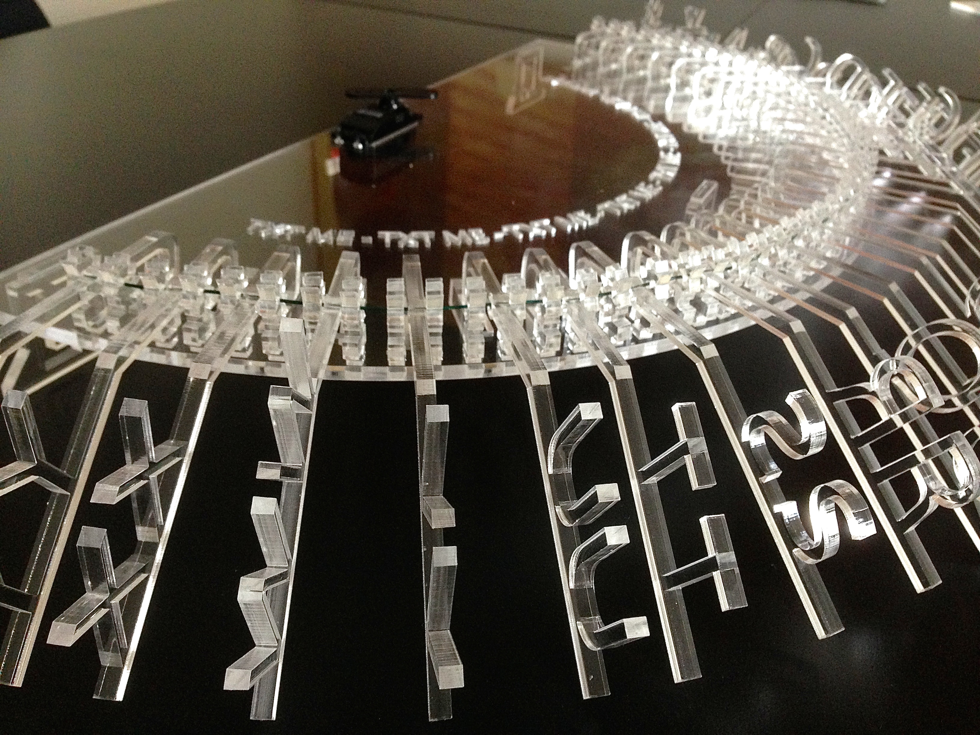
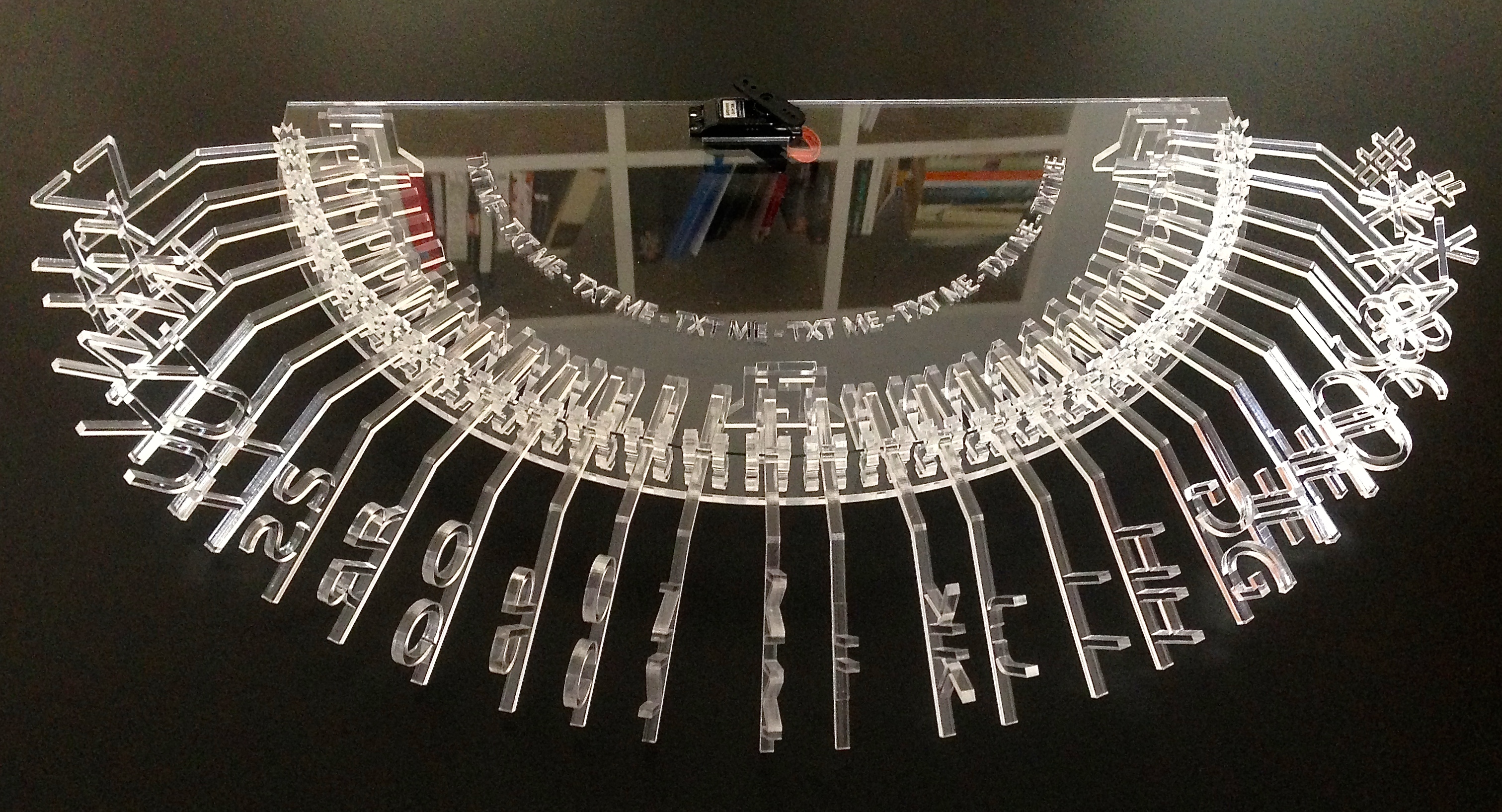
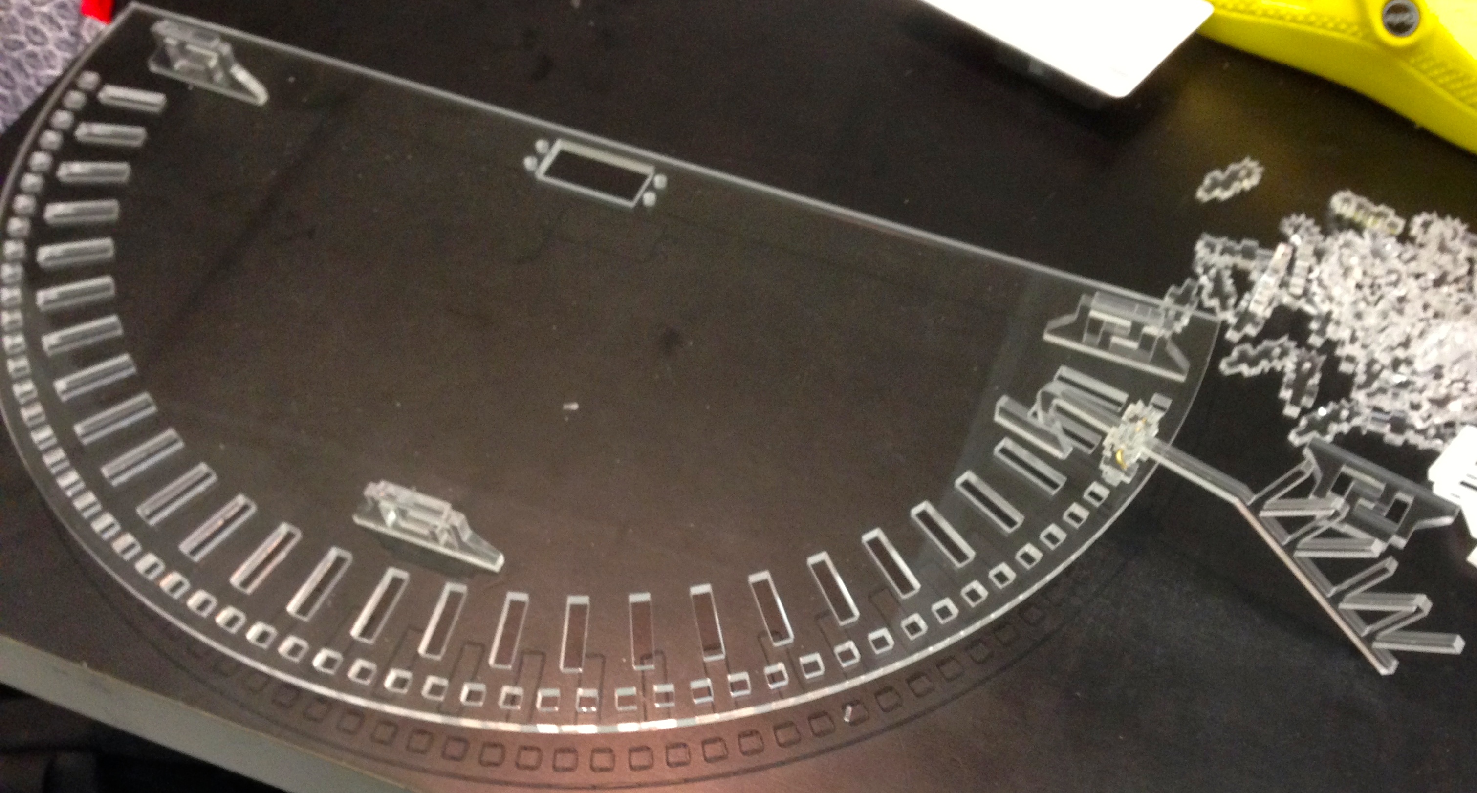
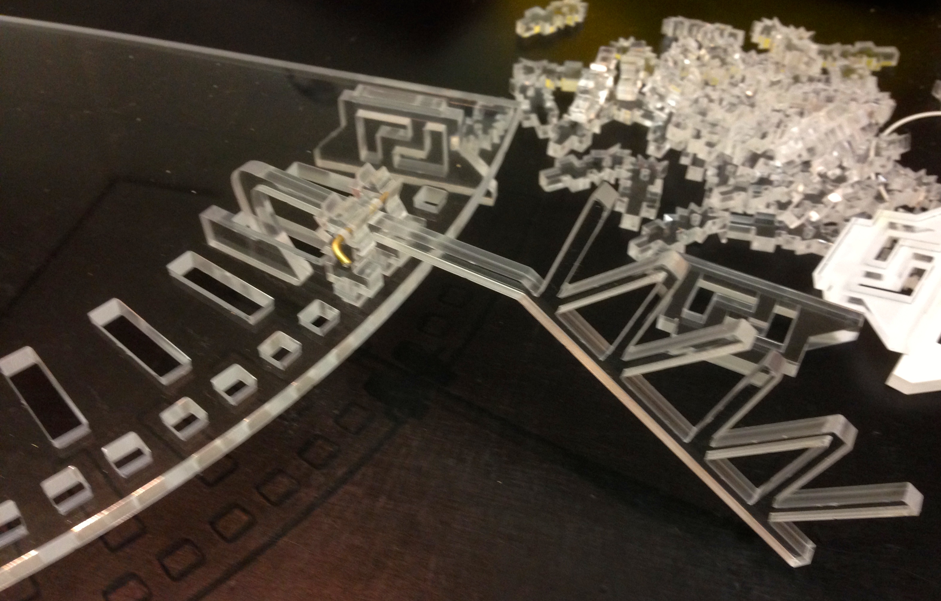
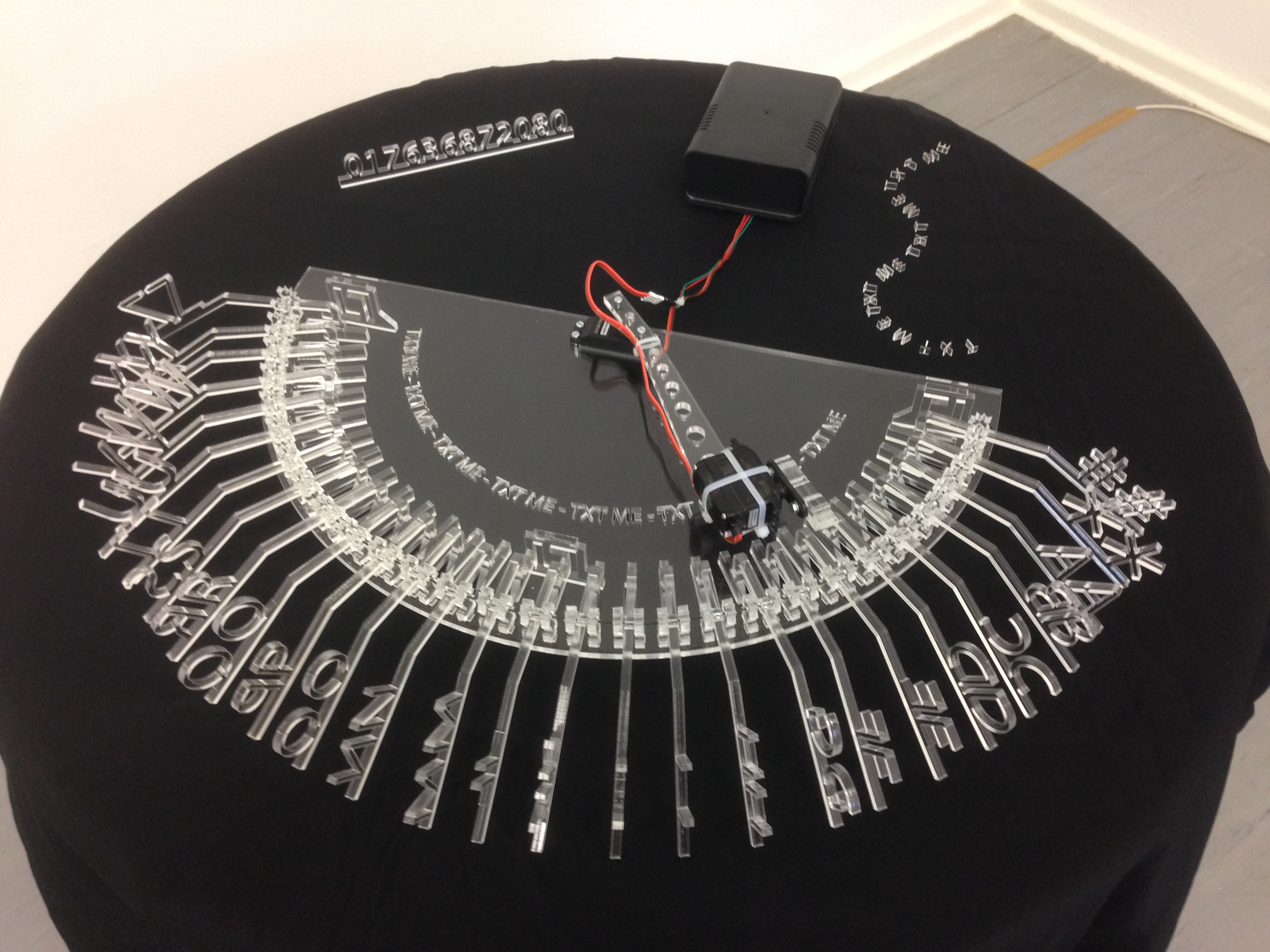
I drew the parts in Inkscape and went to the Fablab to cut 5 mm perspex using their 40 Watt Epilog Zing 6030 laser cutter.
What was difficult?
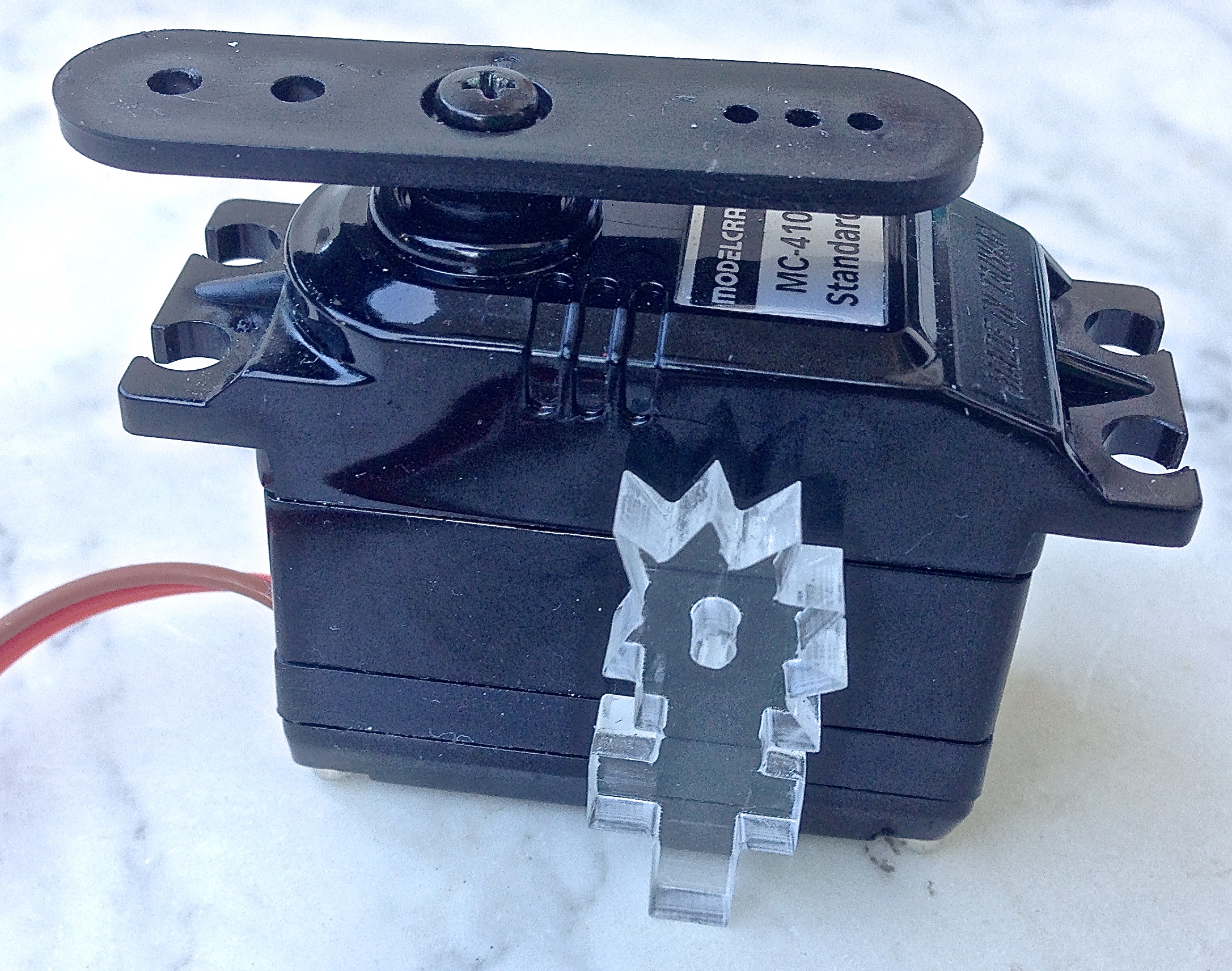
The servomotors were challenging. A 5 Euro servo with plastic gearing from Conrad liked to vibrate incredibly violently when the arm was connected to it and I tried to move it. A 20 Euro servo was stable but did not cover the range of angles that I needed. A 10 Euro servo was stable, but … over the course of a busy evening, the servo motor’s precision varied, so that it started missing the “A” arm completely. On the following morning, it was back to normal. I guess that even more money is required to get a servo which has the required precision, or maybe some external sensors could offer regular auto-calibration.
The Arduino was very sensitive to my soldering iron switching on and off as the iron controls its temperature. As I couldn’t do too much about that, once I had understood what was happening, I added a heartbeat LED which flashes for each pass through the main loop, to give me confidence that the Arduino was still running and not hung up, causing me to look for non-existent faults.
stnfre001
It would be really cool to add a LED light to each letter, so that it lights up, when that letter is displayed.
KronoNaut
I adore this project.
askjerry
I tried to play the video… but it says “Error playing video, video could not be displayed.” Perhaps you can upload it to YouTube and post a link.
crispernakisan
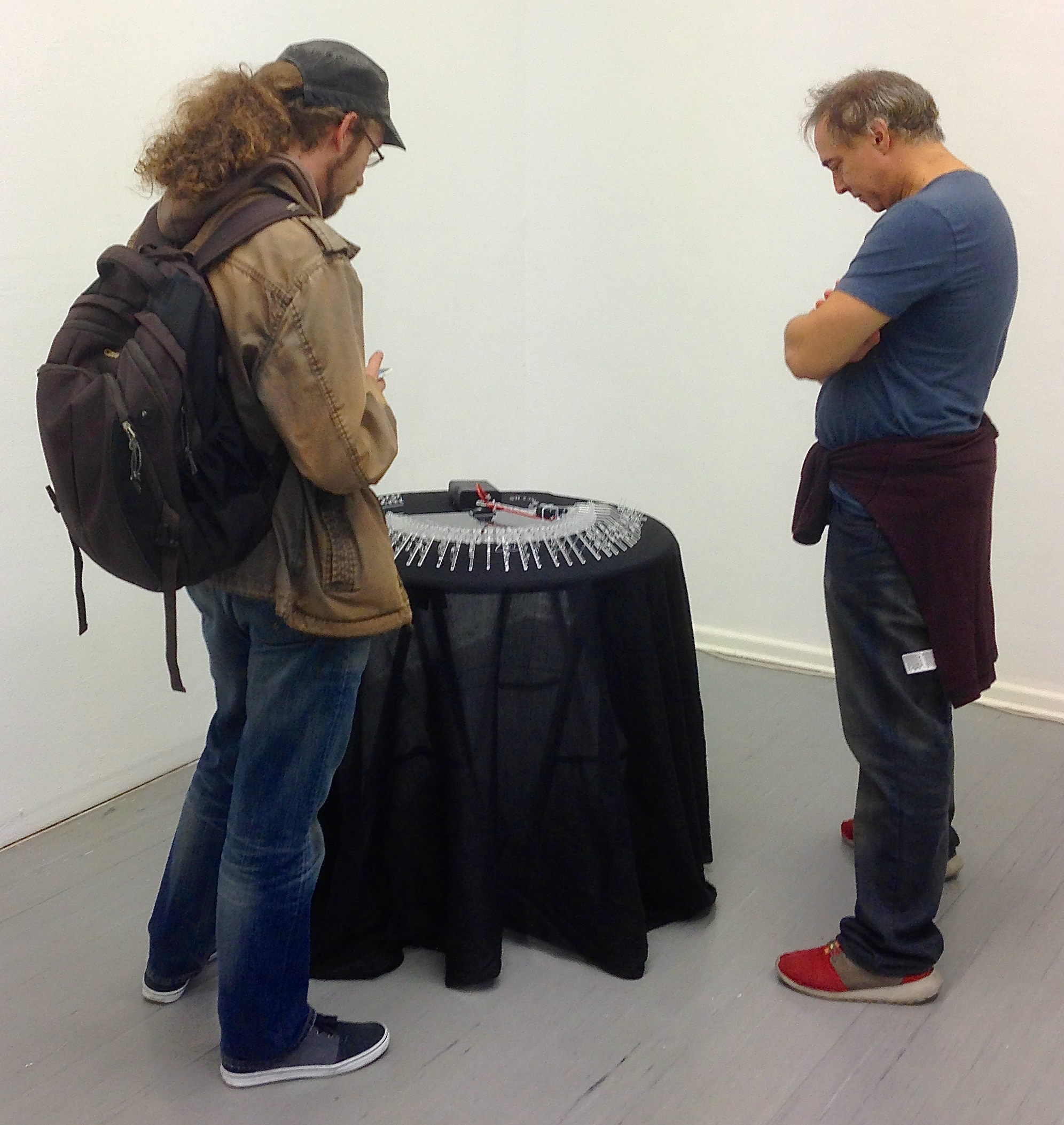
This is pretty sweet. I like the design on the letters themselves, for sure. Yes, please do add a video… but with a short text for those of us with short attention spans. speaking of short attention spans, I’d probably need to add a “replay previous text” button.
crispernakisan
Oh… there is a video!
rimar2000
Very interesting. Maybe a video…
TheB1
Very creative. Though I can’t imagine what will happen the first time someone decides to text and drive with this device.
MsSweetSatisfaction
Definitely a different take on texting than anything else I’ve ever seen. Nice job, and thanks for sharing!
Brandon Sims
Maybe a laser on the arm to illuminate the letter when it pops up.
Fernando Contreras
que hace
Corinne Whittington
COOL
Anthony Borrie
Cool
Put Likes First
We ought to try this stuffs
Crusieth Maximuss Whoa…
John Smith
Neat
On the first day
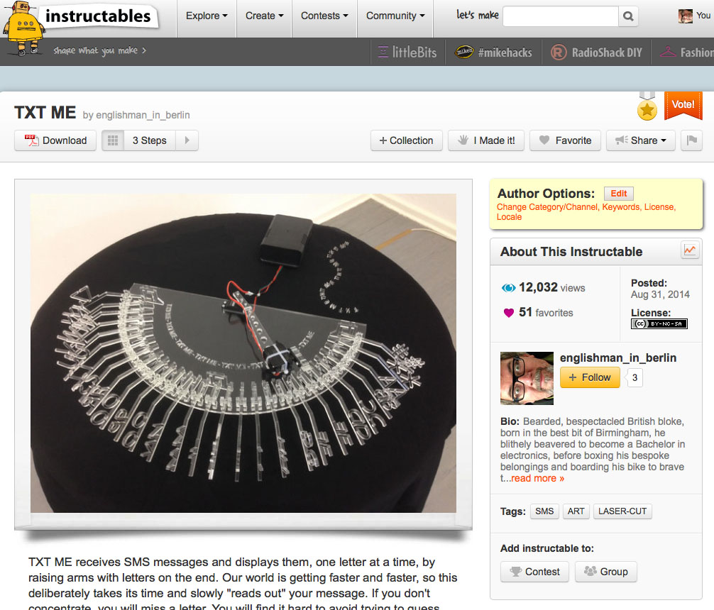
Hi englishman_in_berlin!
Congratulations, your Step by Step Instructable “TXT ME” was just featured by one of our editors! Look for it in the Technology category. Being featured means we think you are awesome. Keep up the great work!
Hello englishman_in_berlin!
Your Step by Step Instructable “TXT ME” just became popular on Instructables!
Being popular means that tons of people are checking out your Step by Step Instructable and telling us they really like it. Keep up the great work!
Congratulations englishman_in_berlin!
“TXT ME” has been featured to the Instructables homepage! Being featured by our editors means your Instructable stands out and represents one of the best we have.
Projects like yours make Instructables a great place, and we really appreciate your time and effort. As a thank you, we’d like to give you a 3 Month Pro Membership to Instructables.
Sorry, the spaces get zapped so this is a bit of a mess.
/*
TEXT ME
This sketch, relying on the Arduino GSM shield, waits for an SMS
message and displays it through the serial port and on Kim's
TEXT ME machine.
Some code from Javier Zorzano / TD
http://arduino.cc/en/Tutorial/GSMExamplesReceiveSMS
*/
/******************************************************************************************
* T H E C I R C U I T
*
* An external power supply is mandatory, otherwise the GSM unit doesn't work
*
* The GSM shield is plugged onto an Arduino Uno
* There are two servos both connected to GND and +5V
* The rotary servo control line goes to pin 5
* The vertical servo control line goes to pin 10
* The ready LED goes to pin 11 via a 200 ohm resistor
* The cathode of the ready LED goes to GND
*
******************************************************************************************/
#include // Include the GSM library
#include // Include the servo library
#define PINNUMBER "XXXX" // PIN number for the GSM SIM card - replace XXXX with actual value
#define rotaryPin 5 // Connect pin 5 to the rotary servo do not use 9 -unstable
#define verticalPin 10 // Connect pin 10 to the vertical servo
#define readyLed 11 // Connect pin 11 to LED which shows that GSM unit is connected
GSM gsmAccess; // Initialise the library instances
GSM_SMS sms;
char senderNumber[20]; // Array to hold the number that an SMS is retrieved from
Servo rotaryServo; // Create servo object to control rotary servo
Servo verticalServo; // Create servo object to control vertical servo
// This is where the "calibrated" values are entered so that the rotary servo moves to the right place to find the letter concerned
int numberOfLetters = 26;
int currentServoPosition;
int newServoPosition;
int up = 170; // Two extremes of vertical servo
int down = 117;
int inactivityTimer = 0;
/**************************************************************************************
* Set up
**************************************************************************************/
void setup()
{
Serial.begin (9600); // Initialise serial communication at 9600
rotaryServo.attach (rotaryPin); // Attach the rotary servo
verticalServo.attach (verticalPin); // Attach the finger servo
boolean notConnected = true; // GSM connection state
parkArm(); // Move to a safe space if not there already
prompt();
parkArm(); // Move to a safe space
while (notConnected) // Wait until GSM connection is established
{
digitalWrite(readyLed, LOW); // Turn the ready LED off
Serial.println ("GSM initialized"); // Confidence building message
Serial.println ("Waiting for messages");
digitalWrite(readyLed, HIGH); // Turn the ready LED on
}
/**************************************************************************************
* Main loop
**************************************************************************************/
void loop()
{
char c;
// If there are no SMSs available at regular intervals make a show
inactivityTimer = inactivityTimer++; // Count up for each loop
if (inactivityTimer > 300) // Approx. 1 sec per loop
{
inactivityTimer = 0; // Reset the tomer
prompt(); // Draw attention to yourself
}
// Heartbeat on LED to show that loop is still looping
digitalWrite(readyLed, LOW); // Turn the ready LED off
delay(100); // Time that LED is off
digitalWrite(readyLed, HIGH); // Turn the ready LED on
// If there is an SMS available
if (sms.available())
{
inactivityTimer = 0; // If message then reset inactivity timer
Serial.println("Message received from:");
// Read message bytes and print them
while(c=sms.read())
{
raiseLetterArm (c); // "Print" to perspex arms
}
sms.flush(); // Delete message from modem memory
}
delay(1000);
}
/**************************************************************************************
* Prompt any users
**************************************************************************************/
void prompt()
{
raiseLetterArm (84); // "Print" TEXT ME to perspex arms
raiseLetterArm (69);
raiseLetterArm (88);
raiseLetterArm (84);
raiseLetterArm (77);
raiseLetterArm (69);
}
/**************************************************************************************
* Put the arm out of harm's way
**************************************************************************************/
void parkArm()
{
rotaryServo.attach (rotaryPin); // Attach the rotary servo
newServoPosition = 180; // Park where the arm can do no harm when switched on/off
currentServoPosition = 9; // Make sure that it is clear that a move is needed
rotateServo(); // Move the rotary servo
delay(2000); // Wait for the servo to get there
rotaryServo.detach (); // Keep things quiet
}
/**************************************************************************************
* Raise the letter arm specified
**************************************************************************************/
void raiseLetterArm (int charEntered)
{
rotaryServo.attach (rotaryPin); // Attach the servo on pin
// 'A' is 65 'a' is 97 'Z' is 90
if ((charEntered < 65) || ((charEntered > 91) && (charEntered < 97))
|| (charEntered > 123))
{
// Then is not A to Z so do nothing - wait a bit
}
else
{
// Make lower case into upper case
if (charEntered > 96)
{
charEntered = charEntered - 32;
}
if ((charEntered > 64)&&(charEntered < 91))
{
newServoPosition = rotation [charEntered - 65]; // Set where to turn the arm to
rotateServo();
}
// Show what was sent:
Serial.print("You sent me: \'");
Serial.write(charEntered);
Serial.print("\' ASCII Value: ");
Serial.println(charEntered);
pressDown ();
}
rotaryServo.detach (); // Stop random movements
}
/*********************************************************************************
* Push the finger down - make sure it is up before returning !
*********************************************************************************/
void pressDown()
{
verticalServo.attach (verticalPin); // Attach the finger servo
delay(500);
for (int i= 0; i < up-down; i++)
{
verticalServo.write (up-i); // Finger down one degree at a time
delay(10);
}
delay(2000);
for (int i= 0; i < up-down; i++)
{
verticalServo.write (down +i); // Finger up one degree at a time
delay(10);
}
delay(500);
verticalServo.detach (); // Stop random movements
}
/*********************************************************************************
* Move the arm around - make sure that the finger is up before using it
*********************************************************************************/
void rotateServo()
{
int difference;
int noOfSlowSteps = 5; // No of degrees to move slowly was 5
int waitForServo = 20; // Do not reduce too much or it misses steps
verticalServo.attach (verticalPin); // Attach the finger servo
verticalServo.write (up); // Make sure it's out of the way
verticalServo.detach (); // Detach
difference = newServoPosition - currentServoPosition;
if (difference > noOfSlowSteps)
{
rotaryServo.write (newServoPosition - noOfSlowSteps); // Quickly move
currentServoPosition = newServoPosition - noOfSlowSteps; // Note new position
}
if (difference < -1*noOfSlowSteps)
{
rotaryServo.write (newServoPosition + noOfSlowSteps); // Quickly move
currentServoPosition = newServoPosition + noOfSlowSteps; // Note new position
}
difference = newServoPosition - currentServoPosition; // Recalculate difference
if (difference > 0)
// Then slowly increase current position until difference is 0
{
for (int i = 0; i < difference+1; i++)
{
rotaryServo.write (currentServoPosition + i);
delay (waitForServo);
}
}
else
// Then slowly decrease current position until difference is 0
{
for (int i = 0; i < (-1*difference)+1; i++)
{
rotaryServo.write (currentServoPosition - i);
delay (waitForServo);
}
}
currentServoPosition = newServoPosition; // Remember where arm is
}
/**********************************************************************************
* windscreen wiper test
**********************************************************************************/
/* for (letter=0; letter < numberOfLetters; letter++)
{
newServoPosition = rotation [letter]; // Set where to turn the arm to
rotateServo();
// Serial.print("rotation [letter] ");
// Serial.println(rotation [letter]);
}
delay(5000);
for (letter=numberOfLetters; letter +1 > 0; letter--)
{
newServoPosition = rotation [letter]; // Set where to turn the arm to
rotateServo();
/**********************************************************************************
* To calibrate the rotary servo
**********************************************************************************/
/* - commented out, define potpin and uncomment to use
val = analogRead(potpin); // Reads the value of a potentiometer connected between +5 and GND on potpin (value between 0 and 1023)
val = map(val, 0, 1023, 0, 179); // Scale it to use it with the servo (value between 0 and 180)
rotaryServo.write(val); // Sets the servo position according to the scaled value
delay(15); // Waits for the servo to get there
// print out the value you read:
Serial.println(val); */
This is related to twelve tweeters, so check them out for more detail on the birds. Guaranteed completely free from electronics. The only digits involved here are those that you were born with.
Bird’s eggs are tricky devils to hold still while drilling carefully angled holes, so a jig to hold them still is a real help.
A vice is OK to cut balls in half, but you need another jig to hold the hemispheres while you chisel or drill holes.
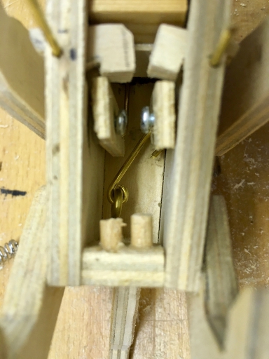
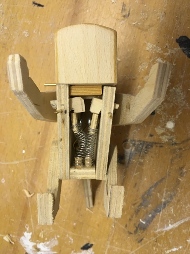
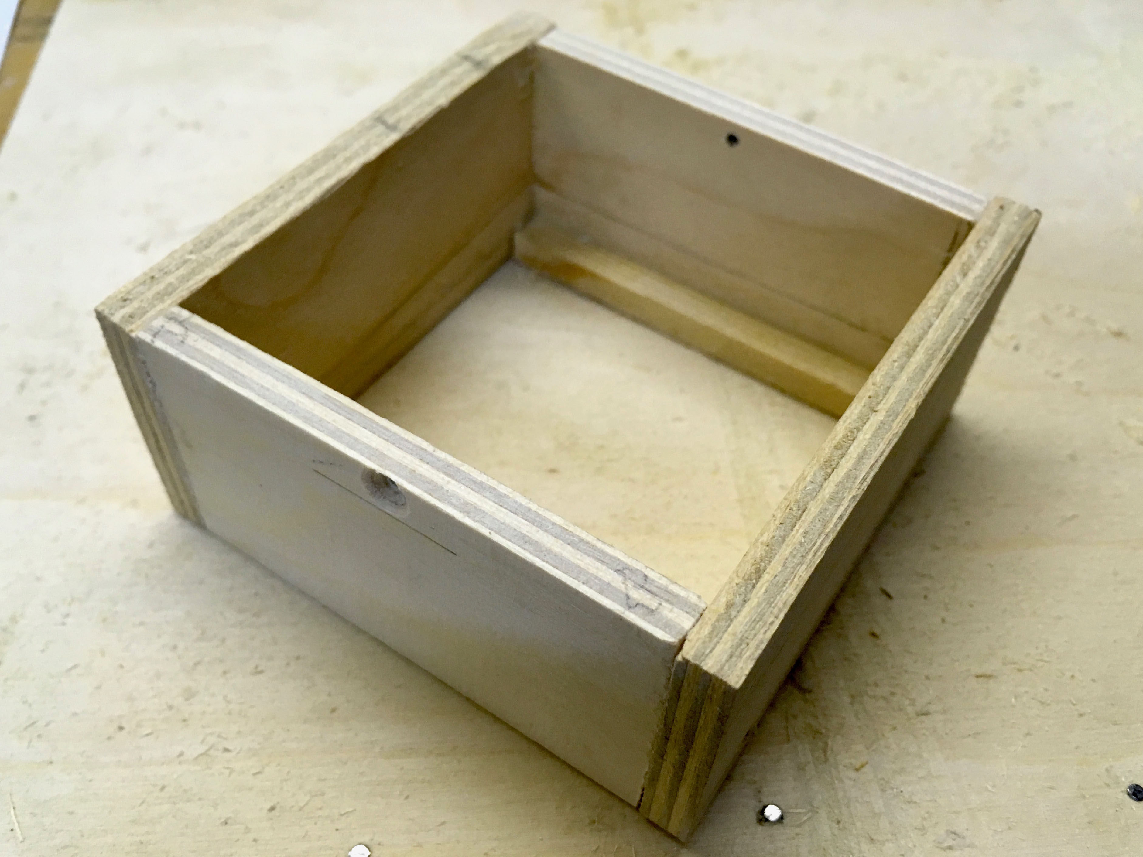
You need a box to put the mechanism in. Note the bar at the bottom to stop the paddles from dropping out.
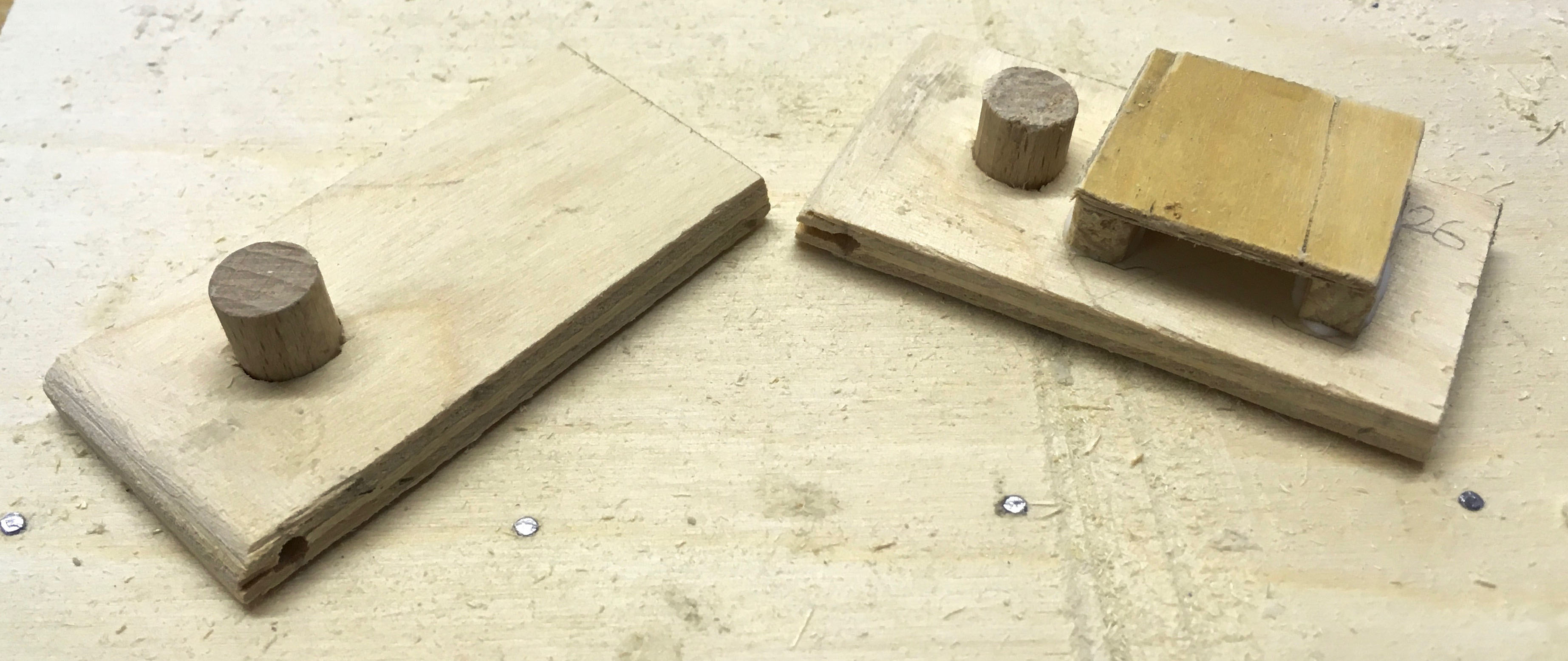
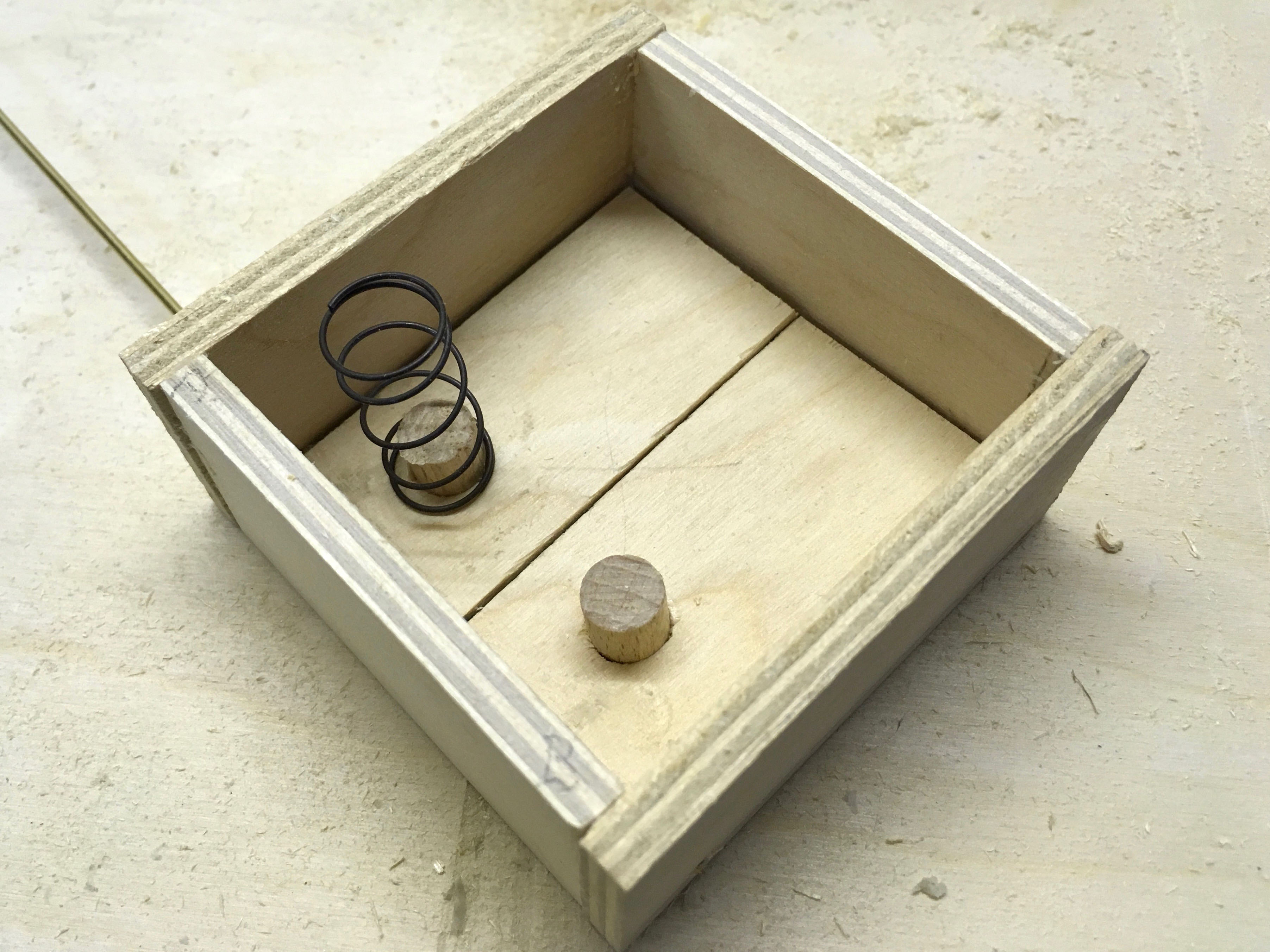
You need two paddles, one to push the head and one for the tail. There is nothing to stop the head from twisting so its paddle has a little extra to stop the brass rod from turning too far. The cylindrical pieces stop the springs from slipping.
The bottom of the box with the paddles inlace, held by the brass rod which goes from side to side of the box.
One of two springs, at the end closer to the hinge to reduce the force.
The bits to make a tail with a hinge hole and a push hole.
It’s tricky to bend the push rods in the right place.
Crest and eyes glued in place. The feet have to wait until the box has been painted.
An Arduino Uno is connected to two HRLV-MaxSonar®-EZ1 ultrasonic sensors, which should measure the range of the nearest objects they can find. By simple triangulation, the single servo controlling the eyes should point them in the right direction.
What’s the problem?
The servos do not provide a stable range reading. The value jumps around for no discernible reason. Maybe the two servos interfere with one another? Theoretically, they are enabled one after the other to prevent that from happening. I need to spend more time diagnosing this. Maybe I should change to a Raspberry Pi and use face recognition?
Strong suspicion
Arduino serial i/f and servo i/f are interfering with one another.
Search using “https://duckduckgo.com/?q=arduino+serial+servo+problem+interrupt&t=osx”
Source code
/****************************************************
* Read the serial output from two ultrasonic sensors
* See http://www.maxbotix.com/Ultrasonic_Sensors/MB1013.htm
* Kim Aug 2014
****************************************************/
#include // Include the library for serial interfaces
#include // Include the library for servos
// Which pins are used for what?
#define txPinLeft 3 // Pin configured but not used as nothing is sent to sensor
#define rxPinLeft 8 // Pin used for serial interface for left MB1013 ultrasonic sensor
// — connects to TX on the ultrasonic sensor
#define txPinRight 5 // Pin configured but not used as nothing is sent to sensor
#define rxPinRight 9 // Pin used for serial interface for right ultrasonic sensor
// — connects to TX on the ultrasonic sensor
#define pinToControlLeftSensor 13 // Pin to enable the left sensor
// — connects to RX on sensor
#define pinToControlRightSensor 12 // Pin to enable the right sensor
// — connects to RX on sensor
#define pinToControlServo 10 // Pin to control the servo
// — connects to orange on the MC410 servo
// — brown on MC410 connects to GND
// — red on MC410 to +5 V
/******************************************************
* MB1013 Ultrasonic pins
* GND connect to GND
* +5V connect to +5 V
* TX left connect to Ard pin 2 right to Ard pin 4
* RX left connect to Ard pin 13 right to Ard pin 12
* AN not connected – analogue output
* BW held low to enable serial interface
******************************************************/
SoftwareSerial serialLeft (rxPinLeft, txPinLeft, true); // Serial port to receive data from left sensor
SoftwareSerial serialRight (rxPinRight, txPinRight, true); // Serial port to receive data from right sensor
// MB1013 output is inverted, so true must be set.
Servo myservo; // Create servo object to control a servo
int lastRangeLeft, lastRangeRight, newRangeLeft, newRangeRight; // Help to elimate odd values
int lastServoPosition =0; // Where the servo was last left least time it was moved
void setup ()
{
Serial.begin (9600); // Start serial port for debug output
serialLeft.begin (9600); // Start serial port for left ultrasonic sensor
serialRight.begin (9600); // Start serial port for right ultrasonic sensor
pinMode (pinToControlLeftSensor, OUTPUT); // Initialize the control pins as outputs
pinMode (pinToControlRightSensor, OUTPUT);
myservo.attach (pinToControlServo); // Attach the servo to the servo object
}
void loop()
{
int servoPosition;
int rangeDifference;
int rangeLeft = readLeft (); // Read left US sensor
int rangeRight = readRight(); // Read right US sensor
/*********************************************
* Calculate difference between the sensors
*********************************************/
rangeDifference = rangeLeft – rangeRight; // What’s the difference in range from the two sensors?
rangeDifference = constrain (rangeDifference, -10, 10); // Limit range difference
Serial.print (” range difference “); // — debug output —
Serial.print (rangeDifference); // — debug output —
servoPosition = map (rangeDifference, -10, +10, 60, 135); // Scale the offset to use it with the servo (value between 0 and 180)
if (lastServoPosition != servoPosition) moveServoTo (servoPosition); // Don’t wake up the servi if there is no need
Serial.print (” servoPosition “); // — debug output —
Serial.println (servoPosition); // — debug output —
}
/********************************************************************
* Function to move the servo at a reasonable speed & keep it quiet
********************************************************************/
void moveServoTo (int servoPosition)
{
int servoDelay = 20; // 10 is OK
myservo.attach (pinToControlServo); // Activate the servo output
if (lastServoPosition > servoPosition)
{
while (lastServoPosition > servoPosition)
{
myservo.write (lastServoPosition–);
delay(servoDelay);
}
}
else
{
while (lastServoPosition < servoPosition)
{
myservo.write (lastServoPosition++);
delay(servoDelay);
}
}
myservo.detach (); // Seems to stop the servo from chattering
}
/***************************************************************
* Function to read the left ultrasonic sensor via a serial port
***************************************************************/
int readLeft()
{
char inData [4];
int index = 0;
digitalWrite (pinToControlLeftSensor, HIGH); // Start the sensor ranging
serialLeft.listen (); // To listen on a port, select it:
while (serialLeft.available () == 0) // Wait for char to be available http://arduino.cc/en/Serial/available
{
}
// Then keep reading serial input until an R appears marking the start of data
char rByte = serialLeft.read ();
while ( rByte != ‘R’)
{
rByte = serialLeft.read ();
}
// Keep looping until four range characters read from sensor
while (index < 4) { if (serialLeft.available () > 0) // When a character is available, put in the array
{
inData [index] = serialLeft.read ();
index++;
}
}
digitalWrite (pinToControlLeftSensor, LOW); // Stop the sensor ranging
return atoi (inData); // Change array of string data into an integer for return
}
/****************************************************************
* Function to read the right ultrasonic sensor via a serial port
****************************************************************/
int readRight ()
{
char inData [4];
int index = 0;
digitalWrite (pinToControlRightSensor, HIGH); // Start the sensor ranging
serialRight.listen (); // To listen on a port, select it
while (serialRight.available () == 0) // Wait for char to be available
{
}
// Then keep reading serial input until an R appears marking the start of data
char rByte = serialRight.read ();
while ( rByte != ‘R’)
{
rByte = serialRight.read ();
}
// Keep looping until four range characters read from sensor
while (index < 4) { if (serialRight.available () > 0) // When a character is available, put in the array
{
inData [index] = serialRight.read ();
index++;
}
}
digitalWrite (pinToControlRightSensor, LOW); // Stop the sensor ranging
return atoi (inData); // Change array of string data into an integer for return
}
/************************************************************************************************************
HRLV-MaxSonar®-EZTM pins – see http://www.maxbotix.com/documents/HRLV-MaxSonar-EZ_Datasheet.pdf
*************************************************************************************************************
Pin 1
Temperature sensor connection
—————————–
Leave this pin unconnected if an external temperature sensor is not used.
Pin 2
Pulse width output
——————
This pin outputs a pulse width representation of the distance with a scale factor
of 1 uS per mm. The output range is 300 uS for 300 mm to 5000 uS for 5000 mm.
The pulse width output is up to 0.5% less accurate then the serial output.
Pin 3
Analog voltage output
———————
On power-up, the voltage on this pin is set to 0V, after which, the voltage on this pin corresponds to the
latest distance measured. The scale factor is (Vcc/5120) per 1 mm. The resolution of the distance is 5 mm.
This is typically within ±10 mm of the serial output.
Using a 10 bit analog to digital convertor, one can read the analog voltage bits (i.e. 0 to 1024) directly
and just multiply the number of bits in the value by 5 to yield the range in mm.
For example, 60 bits corresponds to 300 mm (where 60 * 5 = 300),
and 1000 bits corresponds to 5000-mm (where 1000 * 5 = 5000-mm).
A 5 V power supply yields~0.977 mV per 1 mm.
When powered with 5 V, the output voltage range is 293 mV for 300 mm, and 4.885 V for 5000 mm.
Pin 4
Ranging start/stop
——————
This is internally pulled high. If high, the sensor will continually measure and output the range data.
If low, the sensor will stop ranging.
Take high for 20 uS or longer to initiate a range reading.
If the sensor sees that the RX pin is low after each range reading, then the range can be obtained every 100 mS.
If pin 4 is constantly high, the sensor will range every 100 mS, but the output will pass through a 2 Hz filter.
Pin 5
Serial output
————-
By default, the serial output is RS232 format (0 to Vcc) with a 1 mm resolution.
The output is “R”, followed by four ASCII characters representing the range in millimeters,
followed by a carriage return (ASCII 13). The maximum distance reported is 5000.
The serial output is the most accurate of the range outputs.
Serial data is sent at 9600 baud, with 8 data bits, no parity, and one stop bit.
Pin 6
V+
—
Positive Power
Pin 7
GND
*/
/* The MC 410 standard servo from Conrad
1 brown wire Gnd
2 red wire VCC
3 orange wire PWM signal
For each bird, take one egg 45 x 30 mm, one 30 mm ball, one 15 mm ball with a hole, 13 x 10 mm wooden strip, 8 mm brass tube, small free-moving hinge, 2 mm plywood, 1.2 mm brass rod, 2 mm brass rod
Make 12 birds. Be careful drilling eggs, use pilot holes to prevent the drill slipping. Use a strong glue to fix the hinges but make sure they still move easily. The 1.2 mm brass rod is used to push the beak open until it reaches 45°(ish) and is restrained by the comb when the whole head will move up, exposing the brass neck.
Simple lever on the servo pushes/pulls the brass rod in this prototype. The slot for the brass rod is large enough to accommodate its sideways movement. There is a cross piece soldered to top of rod keep head straight(ish)
The bird’s comb stops beak from opening too far. With the beak fully open, further movement of the rod stretches its neck.
The Base
My base was quite compact. It would be easier to make it larger and space things out.
I used twelve cheap (€6.59) and cheerful servos. I added calibration into the software to deal with the variations in positioning.
The Electronics
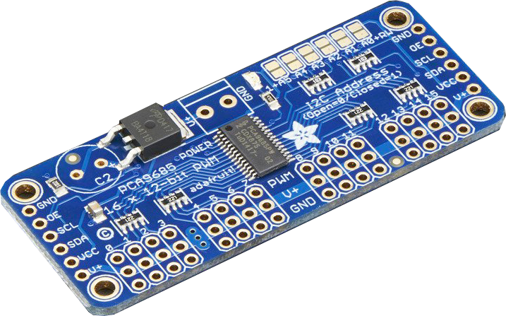
Take one Arduino Uno , one Music Maker shield, one 16 channel PWM driver board with added 2200 µF power smoothing capacitor, one real-time clock board, a micro SD card, a loudspeaker, a pushbutton and a power supply.
Assemble the Music Maker, fit it onto the Arduino, wire up the PWM driver board and RTC. The Music Maker uses the SPI bus. The RTC and the servo driver both use the I2C bus. The default addresses are fine.
Edit
Wenn Sie ein Navigationssystem benutzen geben Sie bitte als Zieladresse die Jakobistraße, Hildesheim ein.
Folgen Sie der Ausschilderung Marktplatzgarage.
Direkt unter dem Hotel befindet sich eine öffentliche Tiefgarage mit direktem Zugang zum Hotel (auf der linken Seite der Einfahrt). Das Parkticket kann an der Hotelrezeption bezahlt werden. Die ermäßigten Kosten für unsere Hotelgäste betragen 9,50 € pro 24 Stunden (Preisänderung vorbehalten).
Führung Samstag, 21. Oktober 2017, von 11:00 Uhr bis 16:00 Uhr
Astenbeck 42
31188 Holle
Deutschland

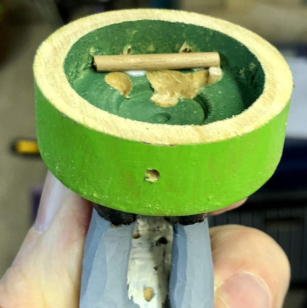
 We need a base for the carrot and the ducats.